Moisture sensor utilizing stereo imaging with an image sensor

a technology of image sensor and moisture sensor, which is applied in image enhancement, vehicle cleaning, instruments, etc., can solve the problems of varying the amount of rain falling on the windshield, relatively expensive processes, and dramatic rainfall rates

Inactive Publication Date: 2005-03-01
GENTEX CORP
View PDF69 Cites 21 Cited by
  • Summary
  • Abstract
  • Description
  • Claims
  • Application Information

AI Technical Summary

Benefits of technology

According to one embodiment of the present invention, a moisture sensing system is provided that reliably distinguishes far field objects, such as vehicle lights and other light sources that may be in the ambient surroundings, from near field images, such as moisture on a vehicle windshield. To achieve these and other aspects and advantages, a system is provided for detecting moisture on a surface that comprises a sensor array having first and second portions, at least one optical system operative to image the same portion of the surface onto both of the portions of the sensor array, and a processing system in communication with the sensor array and operative to analyze images from the first and second portions of the sensor array to detect moisture.
According to another embodiment of the present invention, a moisture sensing system is provided that reliably distinguishes far field objects, such as vehicle lights and other light sources that may be in the ambient surroundings, from near field images, such as moisture on a vehicle windshield. To achieve these and other aspects and advantages, a system is provided for detecting moisture on a surface that comprises first and second sensor arrays spatially offset from one another, at least one optical system operative to image the same portion of the surface onto both of the sensor arrays, and a processing system in communication with the sensor arrays and operative to analyze images from the sensor arrays to detect moisture. The processing system reads image data from at least one row, but less than all rows of the first sensor array and image data from corresponding row(s) of the second sensor array, compares the image data read, and stores the result of the comparison prior to reading image data from additional rows of the sensor arrays.

Problems solved by technology

Unfortunately, the rate of rainfall may vary dramatically over a given period of time.
Additionally, traffic conditions may also cause varying amounts of rain to fall on the windshields, such as when a truck passes by.
As a result, during such conditions, the driver must frequently adjust the wiper time interval, which can be cumbersome.
Unfortunately, such methods require relatively expensive processes, which makes such systems commercially non-viable.
Unfortunately, such optical systems are susceptible to interference from external light sources and thus provide inadequate performance.
Other known systems must be adhered to the windshield, which complicates the windshield replacement.
As a result of such complications, moisture sensors are rarely found on vehicles.
Unfortunately, headlamps of oncoming vehicles will create a bright spot in the image, which would be difficult to completely blur and likely be interpreted as rain.
Moreover, in order for such a system to work effectively, distant objects within the imaged scene must be completely blurred.
Although there is no optical system disclosed in the Japanese laid open patent application for accomplishing this objective, it would be very difficult to develop an optical system to completely blur an oncoming headlamp.
Failure to blur oncoming headlamps could cause false triggering of the system disclosed in the above-identified Japanese laid open patent application.
While this embodiment overcomes some of the problems noted above with respect to the first embodiment, it increases the cost of the system by requiring two separate image sensor arrays.

Method used


Image

  • Moisture sensor utilizing stereo imaging with an image sensor
  • Moisture sensor utilizing stereo imaging with an image sensor
  • Moisture sensor utilizing stereo imaging with an image sensor

Examples


Embodiment Construction

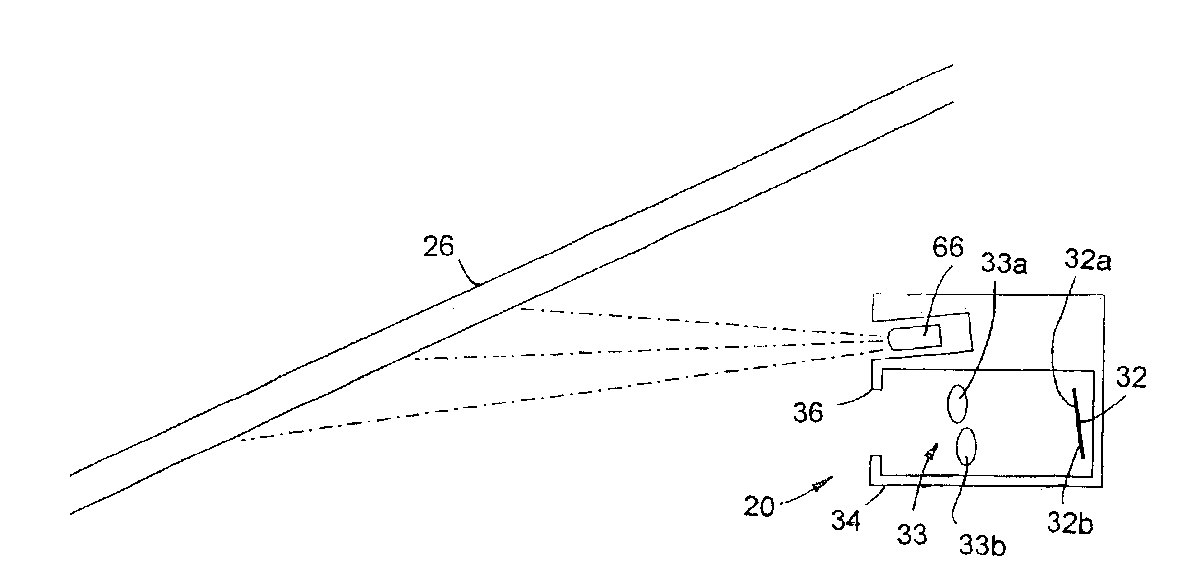
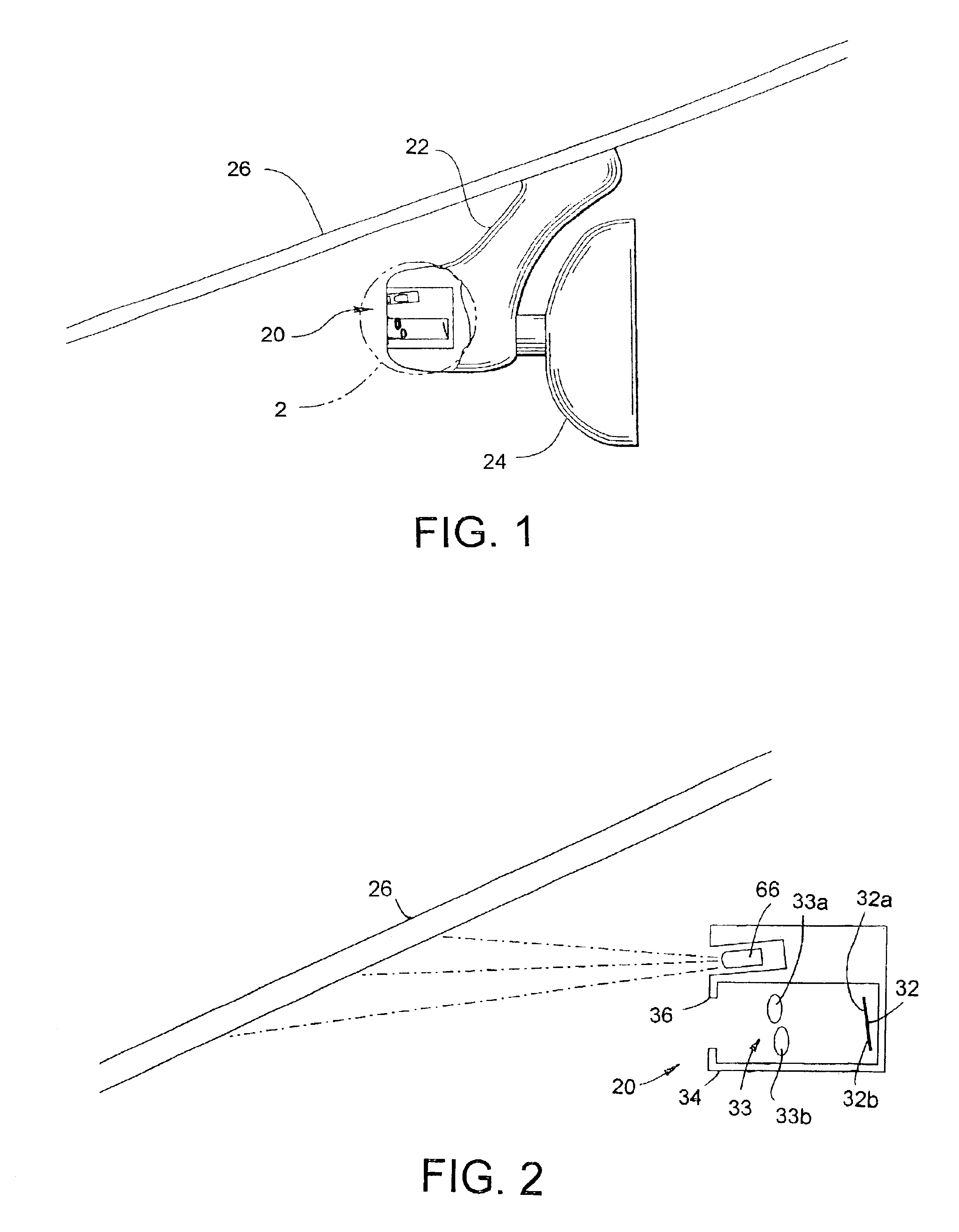
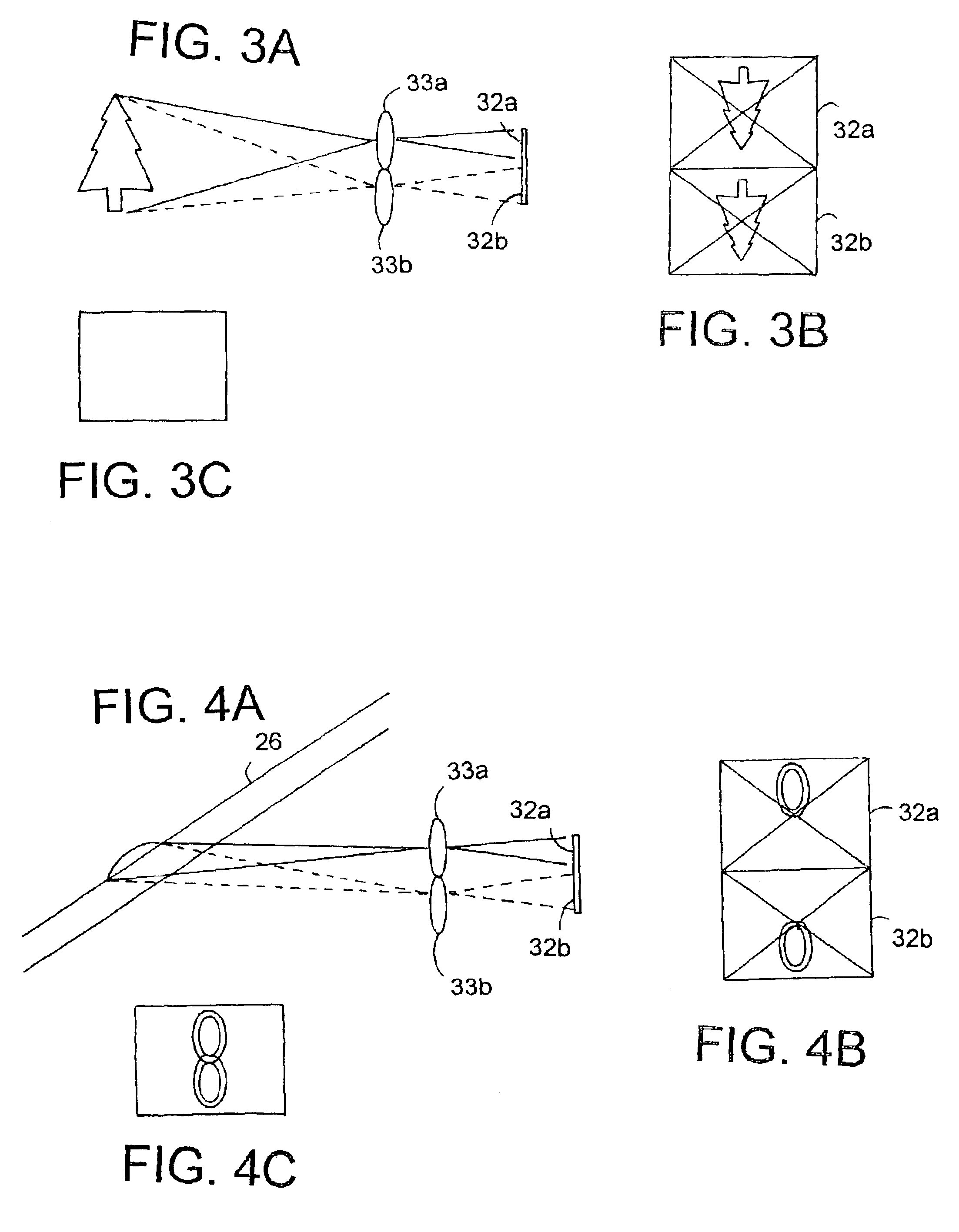
A moisture sensing system in accordance with the present invention is able to detect moisture on a surface such as the windshield of a vehicle. Such a system is useful for automatically controlling the vehicle's windshield wipers, defroster, and / or defogging systems. The system for sensing moisture on a vehicle windshield eliminates many of the performance deficiencies of known moisture sensing systems and provides a moisture sensing system at a commercially viable cost. As used herein, the term moisture is used to designate various types of moisture and precipitation which can be found on the windshield of a vehicle during various climatic conditions, such as rainfall, snow fall, ice, fog as well as other substances that are commonly deposited on a vehicle windshield such as bugs, dust, and the like. The system is able to provide superior performance to other known systems during rather common climatic conditions, such as ice, fog, and varying levels of rain and snow fall and the l...


PUM

PropertyMeasurementUnit
field of viewaaaaaaaaaa
distancesaaaaaaaaaa

Abstract

A moisture sensing system of the present invention includes first and second sensor arrays, at least one optical system operative to image the same portion of the surface onto both of the sensor arrays, and a processing system in communication with the sensor arrays and operative to analyze images from the sensor arrays to detect moisture. The sensor arrays may be two-dimensional sensor arrays that are separate or different portions of the same sensor array. This system may be used to control the windshield wipers of a vehicle. The processing system may be configured to subtract an image obtained from the first sensor array from an image obtained from the second sensor array to distinguish between near field and far field objects.

Description

BACKGROUND OF THE INVENTIONThe present invention relates to a system for automatically detecting the presence of moisture on a surface, such as the surface of a windshield of a vehicle for an automobile, in order to automatically actuate the vehicle's windshield wipers and / or defroster or defogging system.In conventional windshield wiper systems, the windshield wipers are actuated based on the elapsed time between wipes rather than the moisture level on the exterior of the windshield. During conditions of relatively consistent rainfall, for example, the time interval can be adjusted to correspond to the amount of time in which the rain accumulates to the point of the desired visibility level. Unfortunately, the rate of rainfall may vary dramatically over a given period of time. Additionally, traffic conditions may also cause varying amounts of rain to fall on the windshields, such as when a truck passes by. As a result, during such conditions, the driver must frequently adjust the w...

Claims


Application Information

Patent Timeline
Patent Type & Authority Patents(United States)
IPC IPC(8): B60S1/08H04N13/00G01N21/17G01W1/11
CPCB60S1/0818B60S1/0822B60S1/0844G06T7/0022G06T7/0002H04N13/0217B60S1/0833H04N13/0048Y10S318/02H04N13/0253H04N13/0257H04N13/0296H04N2013/0081G06T2207/30268G06T7/97H04N13/254H04N13/257H04N13/161H04N13/296H04N13/218G06V20/56H04N23/811
Inventor OCKERSE, HAROLD C.ROBERTS, JOHN K.
Owner GENTEX CORP
Why Eureka
Try Eureka