Communication system and alarm device

a communication system and alarm device technology, applied in the field of communication systems, can solve problems such as increased costs, and achieve the effects of reducing transmission power, reducing received wireless signals, and reliably distinguishing signals

Inactive Publication Date: 2010-09-02
HOCHIKI CORP
View PDF17 Cites 22 Cited by
  • Summary
  • Abstract
  • Description
  • Claims
  • Application Information

AI Technical Summary

Benefits of technology

[0033]According to the communication system disclosed in (1) above, signals are distinguished based on the first code that differs for each communication device, and the second code defined so as to differ for each communication device on the basis of the first code and the predetermined reference value. Accordingly, the second codes used by the communication devices associated with this communication system do not conflict with the second codes used by the communication devices associated with other communication systems, and signals can be reliably distinguished.
[0034]Further more, with (2) above, in response to predetermined input, a mutual transmission of the first codes takes place between each of the communication devices. Then, based on predetermined rules the single first code is selected and designated the reference value, and the second code is determined from this reference value and the first code of each communication device. Accordingly, the second codes can be assigned that differ for each communication device, and conflict with the second codes used by communication devices associated with other communication systems can be prevented.
[0035]Furthermore, with (3) above, in response to an instruction input from an instruction device of an arbitrary communication device, the first code of that communication device is designated the reference value, and the second code is determined from this reference value and the first code of each communication device. Accordingly, the second codes can be assigned that differ between each communication device, and conflict with second codes used by communication devices associated with other communication systems can be prevented.
[0036]Furthermore, with (4) above, when a new communication device is added to the communication system, the second code of the newly added communication device is determined from the first code and the second code contained in the signals transmitted from the other communication devices, and the first code stored in the storage device. Accordingly, even to newly added communication devices, a second code that differs from other communication devices can be assigned. Further ore, at this time, because no additional setup is required on communication devices that have already been grouped (“grouping” in the context of the present invention means determining second codes and storing the codes in the storage devices of each communication device), the task of adding communication devices can be performed easily.
[0037]According to the first alarm device disclosed in (5) above, when alarm registration is performed to form a different group in a location within a radio range, transmission power is reduced beyond that of normal operation. As a result, the received wireless signal is weakened, and the range of the wireless signal is restricted, thereby preventing the reception of radio waves associated with the alarm registration of other groups and avoiding erroneous registration.
[0038]According to the second alarm device disclosed in (6) above, when alarm registration is performed to form a different group in a location within a radio range, reception sensitivity is reduced beyond that of normal operation. As a result, the range of the wireless signal is restricted, thereby preventing the reception of radio waves associated with the alarm registration of other groups and avoiding erroneous registration.

Problems solved by technology

However, because providing a hard-wired connection between each alarm requires that wiring be installed, a problem arises in terms of increased costs.

Method used


Image

  • Communication system and alarm device
  • Communication system and alarm device
  • Communication system and alarm device

Examples


first embodiment

[0117]First, the first embodiment is described. In this embodiment, either a received first code or a first code stored in the storage device is selected and designated the reference value.

[0118](Communication System Overview)

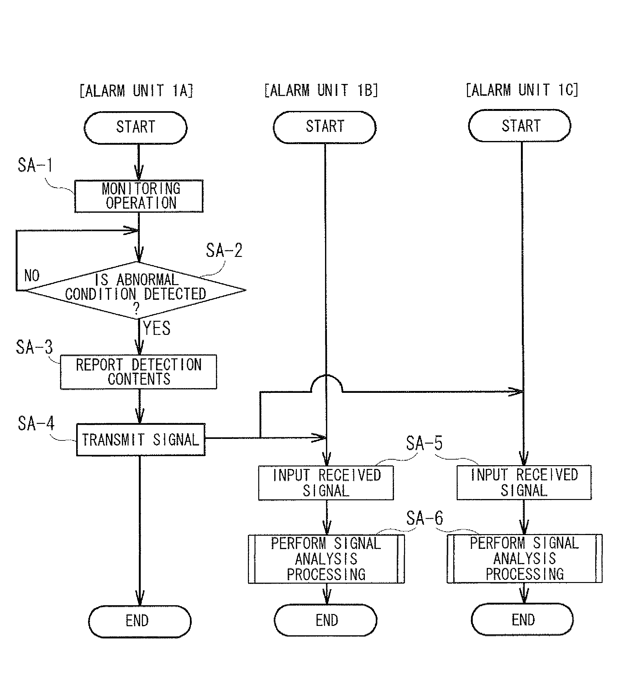
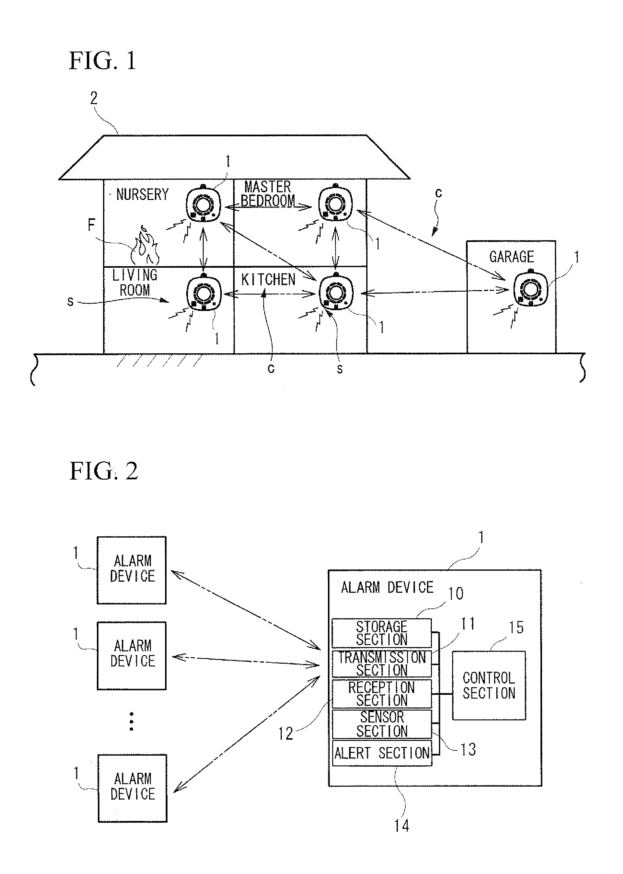
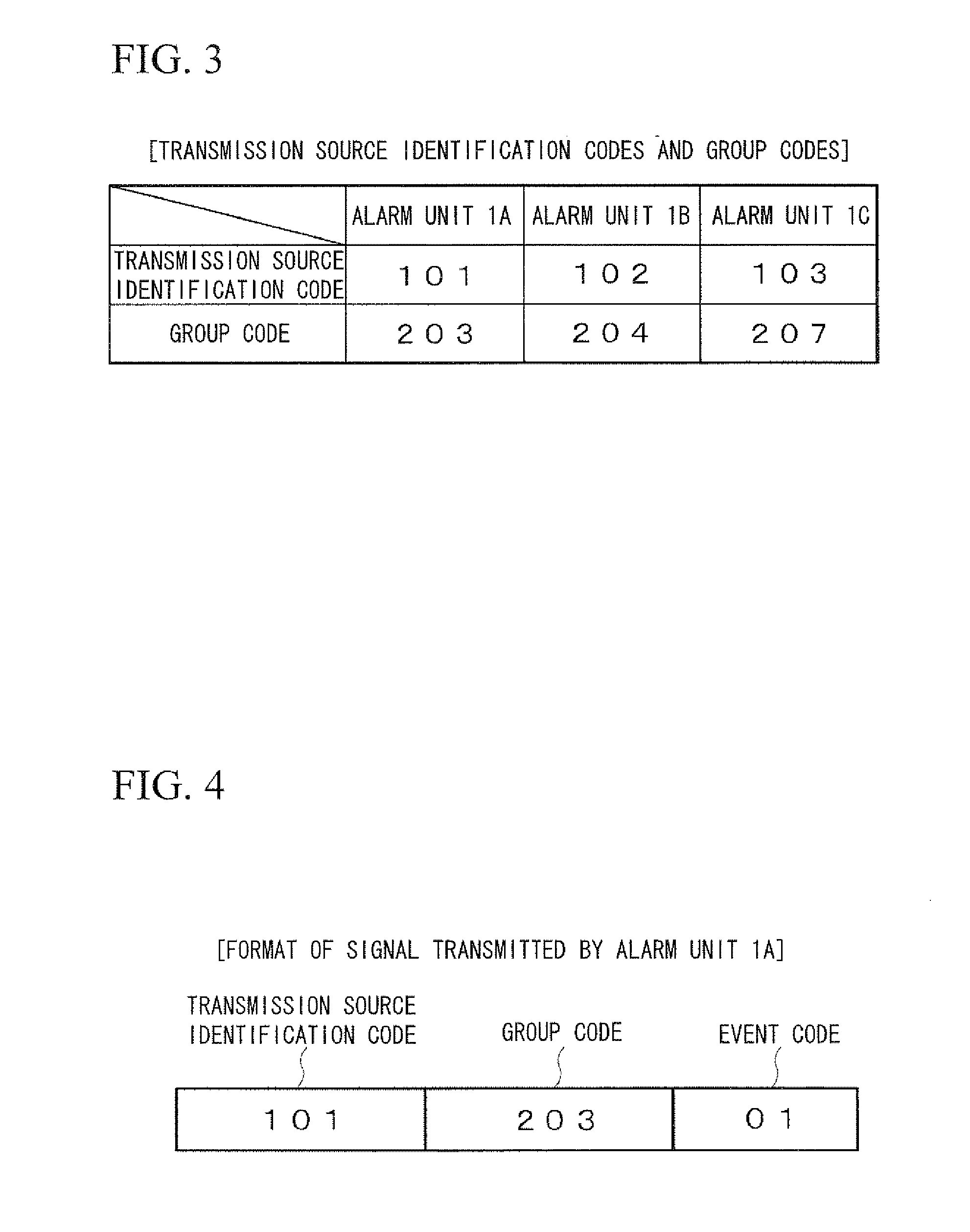
[0119]First, a communication system including a plurality of alarm devices is described in general terms. FIG. 1 is a system diagram showing an overview of a communication system comprising a plurality of alarm devices. In FIG. 1, the letter c indicates communication, and the letter s indicates an alarm (audible alarm). As shown in FIG. 1, in the first embodiment, an alarm device 1 is installed in each room of a residence 2. When a fire or the like occurs in any of these rooms, and is detected by the alarm device 1 in that room, this alarm device 1 emits an alarm and at the same time transmits a wireless signal containing details of the alarm to the alarm devices 1 in the other rooms. The alarm devices 1 in the other rooms, based on the content of the received ...

second embodiment

[0163]Next, a second embodiment is described. This embodiment includes an instruction device to be described later.

[0164]The construction of the present embodiment, except where specifically mentioned, is substantially the same as the construction of the first embodiment, and thus elements which have substantially the same configuration as in the first embodiment are assigned the same reference numerals and / or names as necessary, and description thereof is omitted.

[0165](Construction of Alarm Device 1)

[0166]First, the construction of the alarm device 1 is described. FIG. 9 is a block diagram showing an overview of the construction of the alarm device 1. As shown in FIG. 9, the alarm device 1 includes an instruction switch 16. The instruction switch 16 is for inputting an instruction to the control section 15 that designates the transmission source identification code stored in the storage section 10 as the reference value, and corresponds to the instruction device in the claims. The...

third embodiment

[0189]Hereafter, an alarm device according to a third embodiment of the present invention is described in detail.

[0190]FIG. 11A and FIG. 11B are explanatory drawings showing the outward appearance of a wireless alarm device according to the present embodiment, wherein FIG. 11A shows a front view, and FIG. 11B shows a side view.

[0191]In FIG. 11A and FIG. 11B, an alarm device 110 of the present embodiment includes a cover 112 and a main unit 114. At the center of the cover 112, a smoke detector section 116, having openings through which smoke can enter formed around the periphery thereof, is disposed, which detects a fire when smoke from the fire reaches a predetermined concentration.

[0192]As shown in FIG. 11A, at the lower left side of the smoke detector section 116 of the cover 112, a sound hole 118 is provided. A speaker is housed behind this sound hole 118, such that an audible alarm or voice message can be output through the sound hole 118. Underneath the smoke detector section 1...


PUM


Abstract

A communication system provided with a plurality of communication devices which communicate with each other, wherein each of the communication devices includes: a storage device which stores a first code for identifying the communication device to the exclusion of others, and a second code defined so as to differ from other communication devices on the basis of the first code and a predetermined reference value; a transmission device which transmits a signal including the first code and the second code to the other communication devices; a reception device which receives the signals transmitted from the transmission devices of the other communication devices; and a control device which performs calculation using the first code and the second code included in the signal received by the reception device, and the first code stored in the storage device, and identifies the signal according to whether or not the value obtained by the above calculation matches with the second code stored in the storage device.

Description

TECHNICAL FIELD[0001]The present invention relates to a communication system in which a plurality of communication devices communicate with each other. The present invention also relates to an alarm device which, upon detecting an abnormal condition such as a fire, issues an alarm and also wirelessly transmits a signal to trigger alarms in other alarm devices.[0002]Priority is claimed on Japanese Patent Application No. 2007-268732 and Japanese Patent Application No. 2008-166925, the contents of which are incorporated herein by reference.BACKGROUND ARTFirst Background Art[0003]Conventionally, wireless intercommunication systems in which wireless communication is performed between a plurality of wireless communication devices have been used. These wireless communication devices take signals output from a sensor or received from another communication device, and transmit the signals wirelessly to the other communication devices; and there are examples such as household alarms which det...

Claims


Application Information

Patent Timeline
Patent Type & Authority Applications(United States)
IPC IPC(8): G08B1/08H04Q5/22
CPCG08B21/12G08B21/16G08B25/003G08B25/007G08B25/10H04L61/2069H04L29/12254H04L29/12292H04L41/0681H04L61/2038H04L12/2827H04L61/5038H04L61/5069G08B3/10G08B5/22G08C17/02
Inventor EGAWA, YOSHITAKA
Owner HOCHIKI CORP
Why Eureka
Try Eureka