Method and system for analyzing transmitted signals from a probe system

a technology of transmitted signals and probe systems, applied in the direction of mechanical measuring arrangements, instruments, and mechanical means, can solve the problems of interference signals, becoming increasingly difficult to distinguish between transmitted signals relevant to analysis of probe systems, etc., and achieve the effect of reliable identification

Active Publication Date: 2005-08-02
DR JOHANNES HEIDENHAIN GMBH
View PDF17 Cites 21 Cited by
  • Summary
  • Abstract
  • Description
  • Claims
  • Application Information

AI Technical Summary

Benefits of technology

[0010]Based on the reference signal formed, which defines a signal threshold that is used as a basis for distinguishing the transmitted signals of the probe system from interference signals, by combining the received signals of the probe system with the interference signals, it is possible to ensure that the signal threshold has a value that is not (or in any case very seldom) exceeded by the interference signals. This may prevent interference signals from being mistakenly identified as transmitted signals of the probe system.
[0017]By differentiating the received signals, low-frequency interferences, which occur, for example, in rooms or spaces illuminated by neon tubes, may be eliminated, the analysis method being substantially enhanced in the process with respect to its insensitivity to interference.
[0021]By determining the temporal position of the ascending and descending signal edges of the start and stop signals which have predefined characteristic intervals, the occurrence of start and stop signals at regular intervals may be determined. This may make it possible to reliably distinguish signal packets limited by start and stop signals, from interference signals which do not exhibit any comparable regularity. Because the switch-on signals are emitted in response to each deflection of the probe element, in turn, at a defined position between a start and a stop signal, they are also able to be clearly identified on the basis of the position of their edges with respect to the start and stop signals. The same holds for battery signals or other relevant transmitted signals of the probe system. This may make it possible to further enhance the process of distinguishing the transmitted signals of the probe system relevant to the analysis, from interfering background signals.
[0028]An exceptional reliability of the method may be achieved when, following differentiation of the received signals, the signal edges having a positive and negative slope are each processed and analyzed in a separate circuit.

Problems solved by technology

In this context, it is becoming increasingly more difficult to distinguish between transmitted signals of the probe system relevant to the analysis, and interference signals, because a data exchange between the probe system and the corresponding receiving unit is required over ever greater distances and, associated with this is also often a corresponding enlargement of the solid angle within which the transmitted signals are radiated.

Method used


Image

  • Method and system for analyzing transmitted signals from a probe system
  • Method and system for analyzing transmitted signals from a probe system
  • Method and system for analyzing transmitted signals from a probe system

Examples


Embodiment Construction

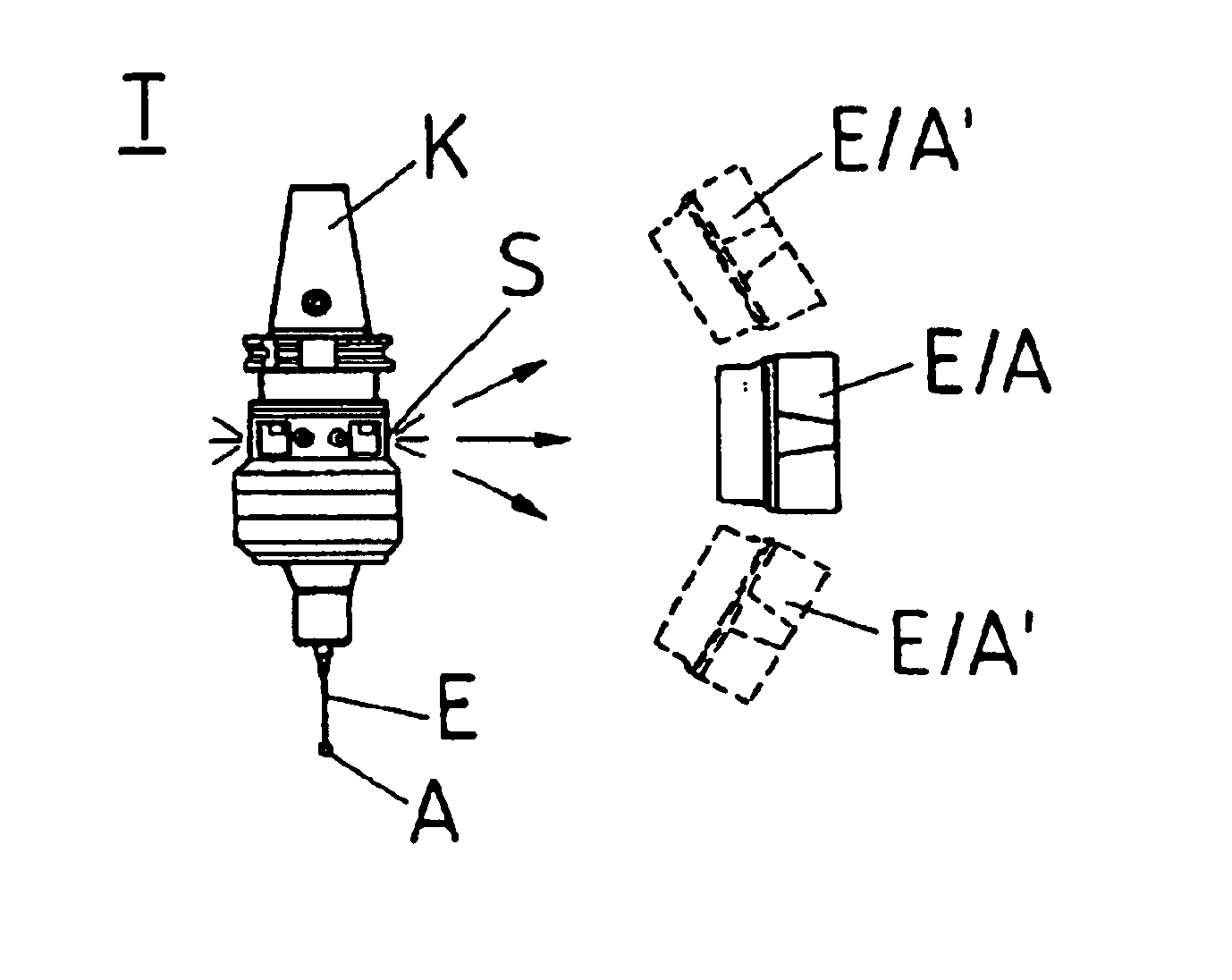
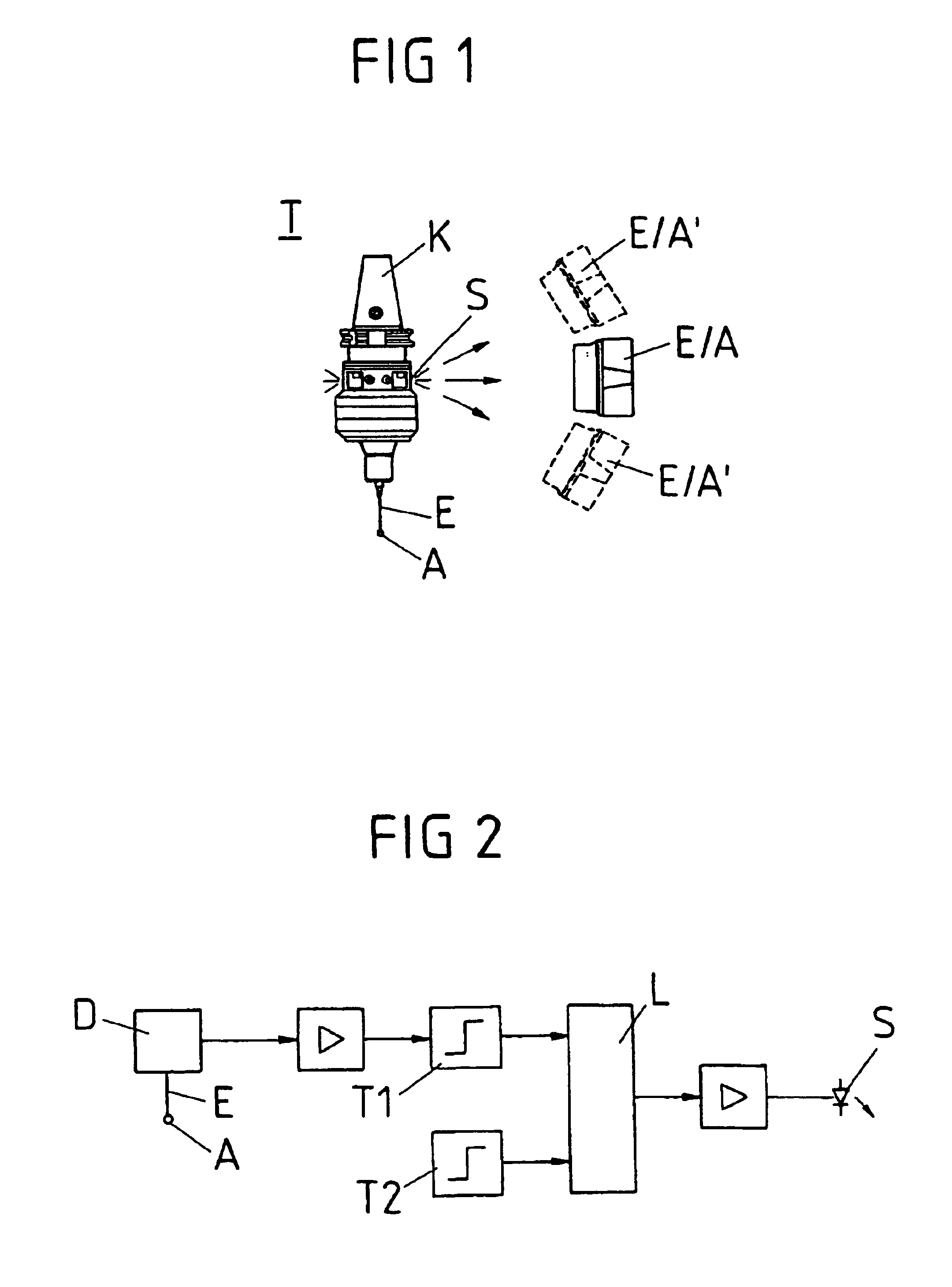
[0084]FIG. 1 illustrates a probe system T, which is used to determine the position and contour of a workpiece clamped in a machine tool, for example, a milling machine and, to this end, includes a measuring probe. Through the use of a cone K, the measuring probe is insertable into a spindle of the particular machine tool.

[0085]At its end opposing cone K, probe system T has a probe element E in the form of a feeler having a probing contact sphere A, which is movably supported in all directions on the housing of the probe system. Typically, the rest position of probe element E is on the axis of symmetry of probe system T, as illustrated in FIG. 1. When probing contact sphere A of probe element E makes contact with a workpiece clamped in the machine tool in question, probe element E is deflected out of its rest position. This deflection is recorded by a detector system of the probe system.

[0086]For this purpose, as illustrated in FIG. 2, the probe system has a detector system D, which ...


PUM


Abstract

A method and a system is for evaluating the transmitted signals of a probe system, which has a probe element that is deflectable out of a rest position and which generates transmitted signals, which include a switch-on signal during a deflection of the probe element out of its rest position and which, together with interference signals, are transmitted to a receiving unit, in which the received signals made up of the transmitted signals and the interference signals, are compared to a reference signal. In this context, the reference signal is formed by interlinking information signals generated from the received signals, and the interference signals, and / or the received signals are differentiated by time, prior to the comparison with the reference signal.

Description

CROSS-REFERENCE TO RELATED APPLICATIONS[0001]The present application claims priority to Application No. 103 04 193.1, filed in the Federal Republic of Germany on Jan. 29, 2003, and to Application No. 103 04 195.8, filed in the Federal Republic of Germany on Jan. 29, 2003, each of which is expressly incorporated herein in its entirety by reference thereto.FIELD OF THE INVENTION[0002]The present invention is directed to a method for analyzing transmitted signals from a probe system and to a system for that purpose.BACKGROUND INFORMATION[0003]What is concerned here is the evaluation of the transmitted signals (output signals) of a probe system, which, on a measuring probe, has a probe element that is deflectable out of its rest position and which, in response to a deflection of the probe element out of its rest position, generates a switch-on signal. Probe systems of this kind are used for determining the position of workpieces which are clamped in material-working machines, such as mi...

Claims


Application Information

Patent Timeline
Patent Type & Authority Patents(United States)
IPC IPC(8): G01B21/02G01B21/04G01B5/008G01B5/012
CPCG01B5/012G01B21/047G01B2210/58
Inventor GROELL, KLAUSEISENBERGER, CHRISTIAN
Owner DR JOHANNES HEIDENHAIN GMBH
Why Eureka
Try Eureka