A transformer arrangement

A transformer and reactor technology, applied in the field of transformer devices, can solve the problems of material consumption and transformer device weight, etc., and achieve the effect of reducing weight and being easy to manufacture

Inactive Publication Date: 2010-02-03
哈克萨弗尔默公司
View PDF0 Cites 0 Cited by
  • Summary
  • Abstract
  • Description
  • Claims
  • Application Information

AI Technical Summary

Problems solved by technology

And because the transformer device is heavy and requires relatively expensive materials, there i

Method used


Image

  • A transformer arrangement
  • A transformer arrangement
  • A transformer arrangement

Examples


Embodiment Construction

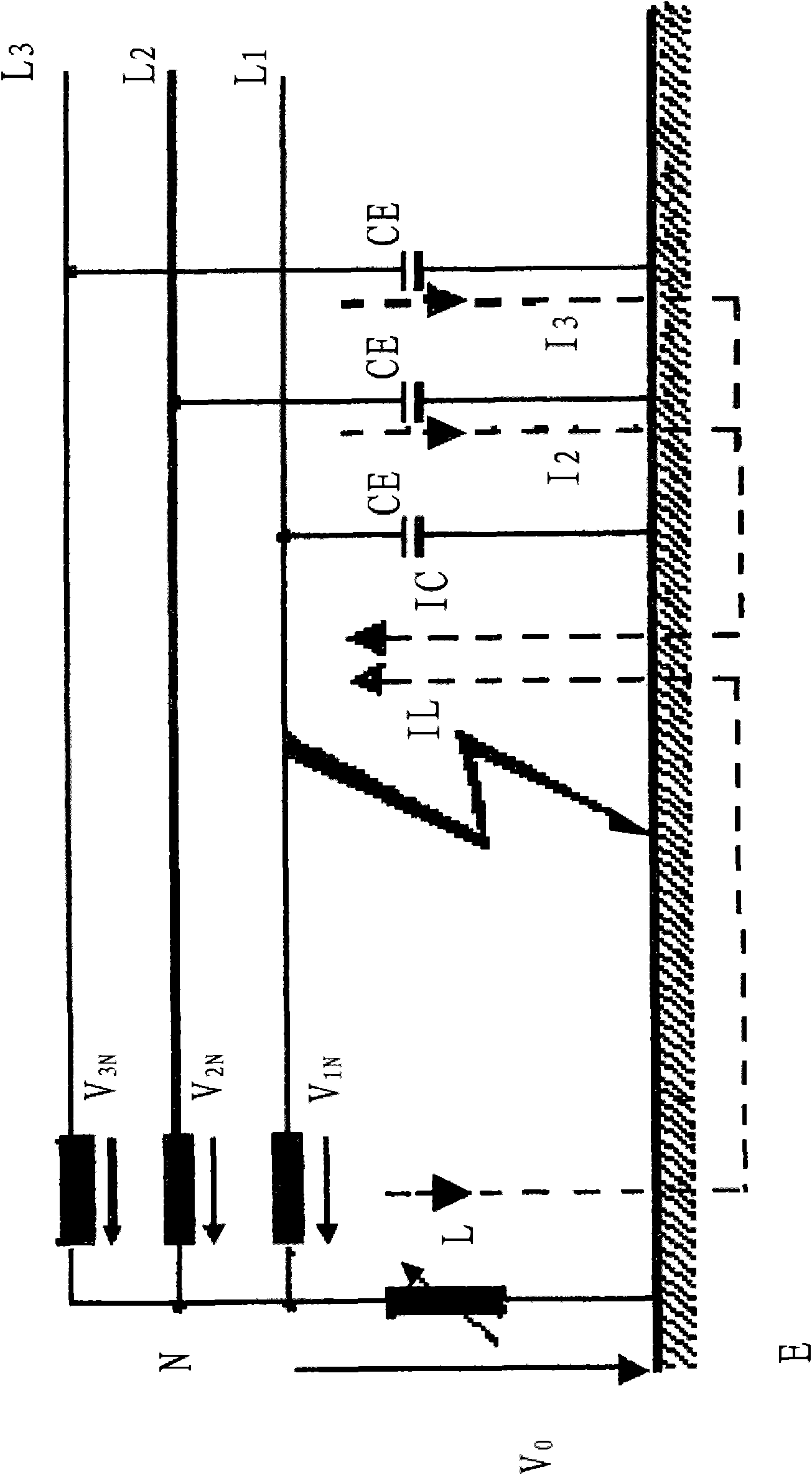
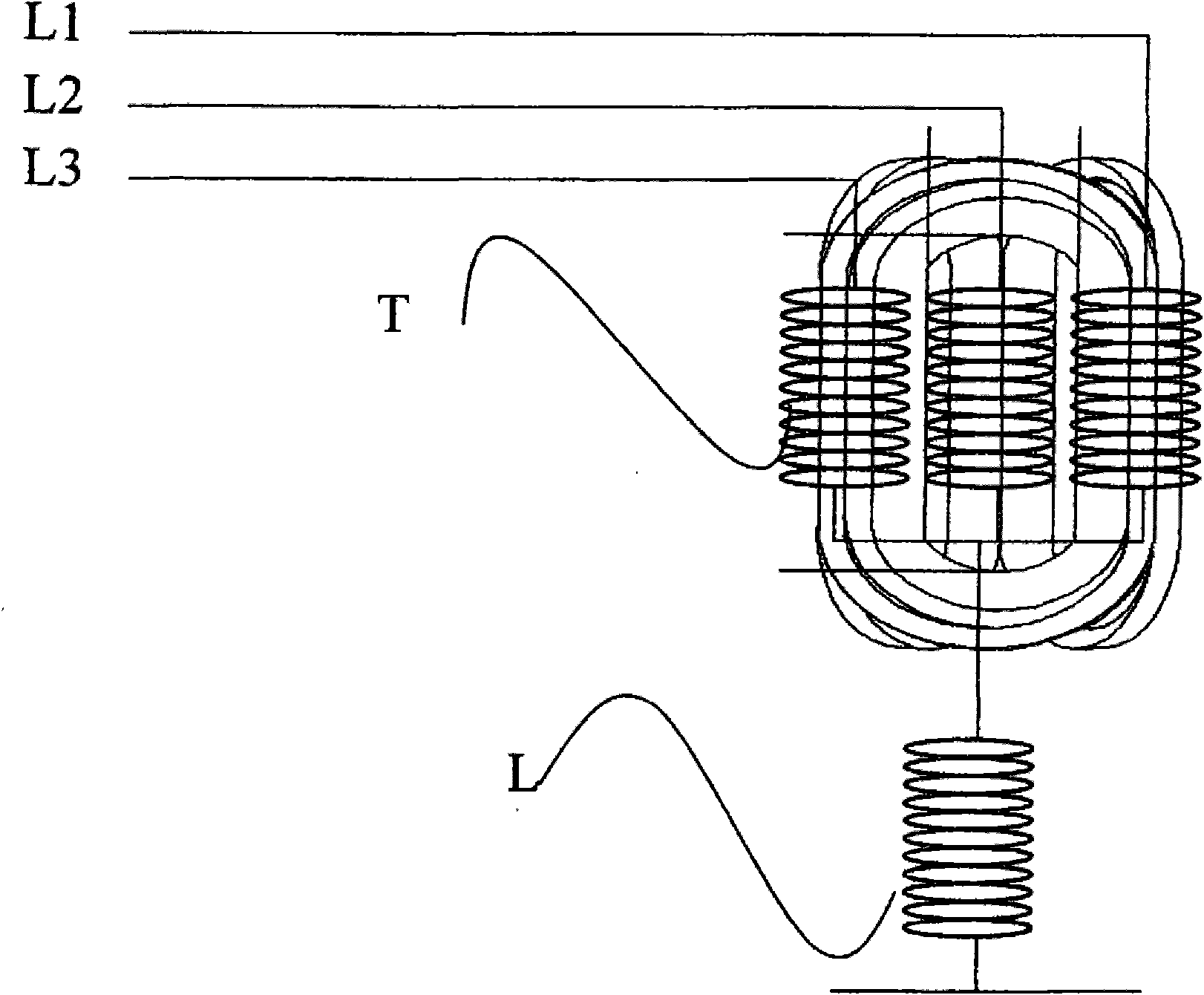
[0019] exist figure 1 , a schematic diagram of a power transmission system with three phases is shown. The system consists of a transformer connected to Y or Z and provided with a crowbar (L). The arc suppression coil (L) is interconnected with the neutral line (N) and ground (E) of the primary side of the transformer. Any one of the three phases is respectively connected to a capacitive loss capacitor (capacitive losses CE). When the three phases of the power transmission line are placed close together, such as in an underground cable, in this case the capacitive loss capacitance will become larger compared to the power transmission line in the air, but although smaller than the underground cable , the aerial power transmission line still has capacitive losses.

[0020] In the event of a ground fault in any phase of L1, L2 or L3, the arc suppression coil (L) will generate a reactive current (IL) that begins to flow in the system due to the ground fault. , Ic) for compensa...


PUM


Abstract

A transformer arrangement comprising a transformer having a neutral and formed as a symmetrical transformer, in particular a cage transformer and having a reactor coil connected to the neutral of thetransformer is provided. The transformer can be of any type having a neutral such as a Y-n/Y-n, Z-n/Z-n, Y-n/Z-n or a Z-n/Y-n transformer. By providing a transformer having symmetrical phases connected to a reactor coil a transformer arrangement having less weight is obtained. The lower weight is obtained because in comparison to using an E core for the transformer all phases will be symmetrical so that if a ground fault occurs in one of then phases there is no need for any compensatory windings regardless of which phase suffers the ground fault.

Description

technical field [0001] The present invention relates to a transformer device, in particular to a transformer device comprising a transformer to which a reactor is connected for interconnecting the transformer with ground. Background technique [0002] Electricity distribution is the penultimate stage of delivering electricity (before sales) to end users. This process is generally considered to include medium voltage power lines (typically less than 50 kV), power substations and transformers equipped with magnetic poles, and low voltage power lines (generally less than 1 kV). [0003] Reactor windings are often used in transformer installations for power distribution. Reactor windings are used to generate reactive power. Reactor windings are used in many different environments. One application of reactors is as a ground, used to change current in power transmission systems. Reactors can thus be designed and used to limit capacitive currents at ground faults to almost zero...

Claims


Application Information

Patent Timeline
IPC IPC(8): H02K9/08
CPCH02H9/08
Inventor 昂内·费尔丁弗雷德里克·格里瓦斯
Owner 哈克萨弗尔默公司
Why Eureka
Try Eureka