


Quick Research
Generate reliable direction feasibility study reports for your R&D in just a few steps.

Technical Q&A
Discover and master advanced knowledge NOW. Basics, ideas, possibilities, all at once.

Find Solutions
As an expert in R&D theories, this can generate solutions to your technical problems instantly.

Evaluate Feasibility
Analyze your overall solution with one click, know your potential R&D risks in advance.

Monitor Landscape
Get weekly tech updates, stay abreast of the latest tech innovations and key insights.
Electric discharge lamp operating device, lighting equipment and lighting system
A technology for lighting devices and discharge lamps, applied in the field of lighting systems, can solve the problems of flickering, long time consumption, etc.
- Summary
- Abstract
- Description
- Claims
- Application Information
AI Technical Summary
Problems solved by technology
Method used
Image

Examples
Embodiment approach 1
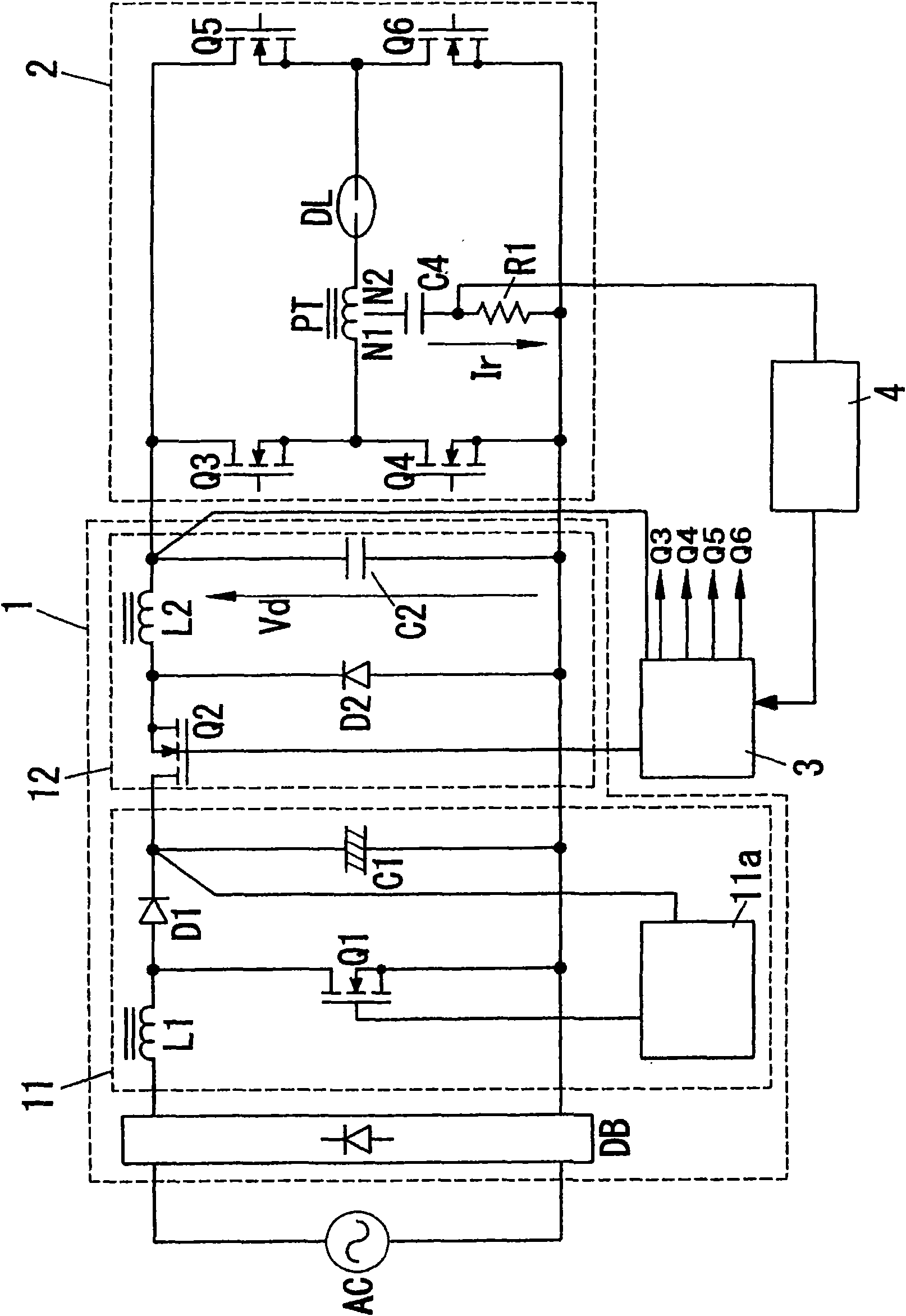
[0071] In this embodiment, if figure 1 As shown, there are: DC power supply circuit 1, which uses AC power supply AC to generate DC power; converter circuit 2, which converts the DC voltage output by the DC power supply circuit into AC voltage, and supplies it to the discharge lamp. The discharge lamp DL is constituted by a so-called high-pressure discharge lamp.
[0072] 【0028】
[0073] The DC power supply circuit 1 has: a diode bridge DB, which performs full-wave rectification on the AC input from the AC power supply AC; a booster unit 11, which smoothes and boosts the voltage output from the diode bridge DB; a voltage drop unit 12 , which steps down the voltage output by the booster 11 . The booster 11 is a known booster converter that takes the voltage across the capacitor C1 as the output voltage, and is composed of the following parts: an inductor L1 connected between the DC output terminals of the diode bridge DB, a diode D1 and a series circuit of capacitor C1; swi...
Embodiment approach 2
[0092] Since the basic configuration of the present embodiment is the same as that of Embodiment 1, the same reference numerals are attached to the common parts and descriptions thereof are omitted, and only different parts will be described.
[0093] 【0038】
[0094] In this embodiment, if Figure 5 As shown, the step-down unit 12 is not provided in the DC power supply circuit 1 , and the output voltage of the boost unit 11 becomes the output voltage of the DC power supply circuit 1 .
[0095] 【0039】
[0096] In addition, there are: a capacitor C3 connected in parallel to the series circuit of the pulse transformer PT and the discharge lamp DL; and an inductance L3 connected between the connection points of the discharge lamp DL and the switching elements Q5 and Q6.
[0097] 【0040】
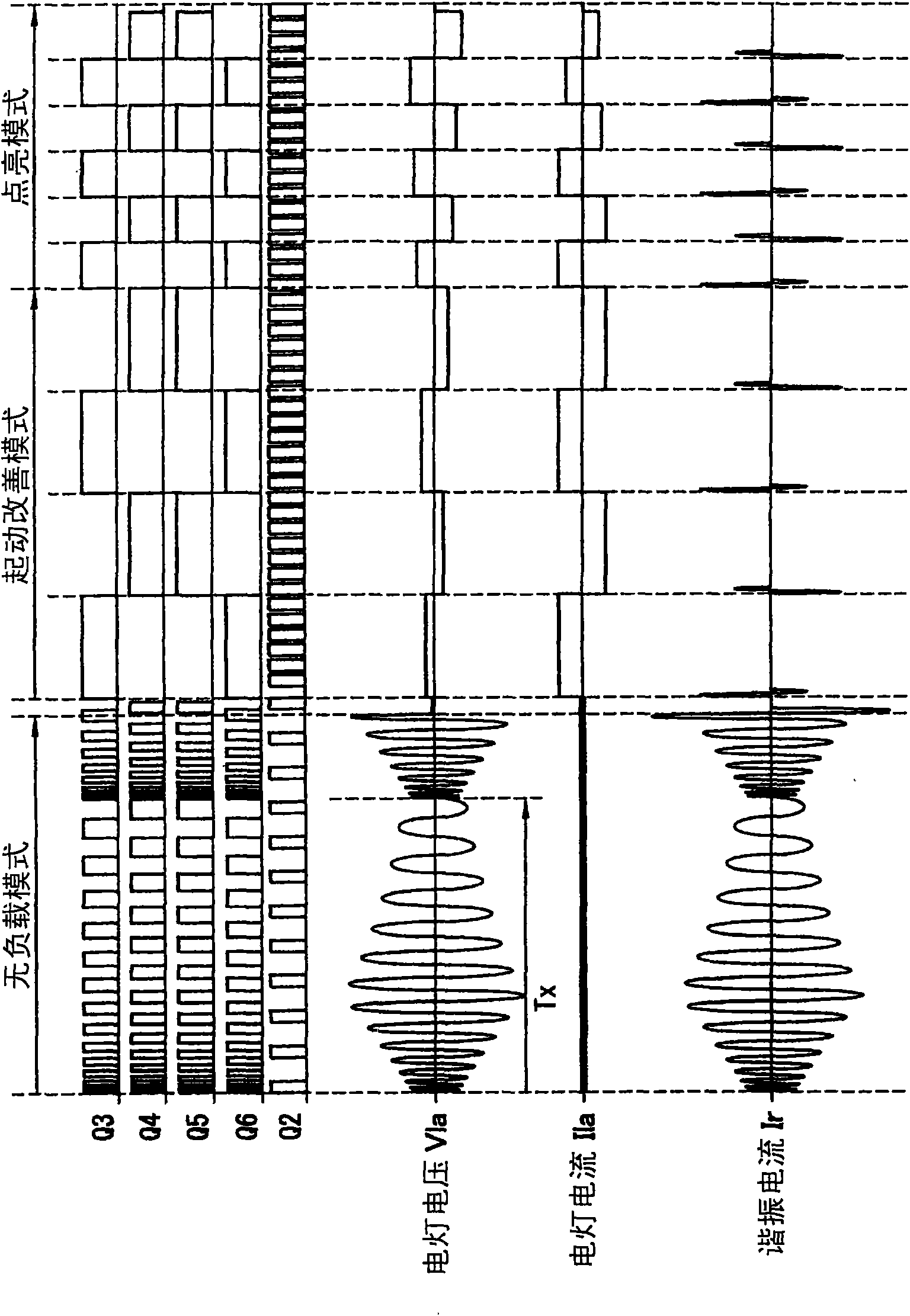
[0098] In this embodiment, if Image 6 As shown, during one cycle (on and off) of the switching elements Q3 to Q6 of the converter circuit 2, the phase of the voltage (lamp voltage) Vla at bot...
PUM
 Abstract
Description
Claims
Application Information
 - R&D Engineer
- R&D Manager
- IP Professional
- Industry Leading Data Capabilities
- Powerful AI technology
- Patent DNA Extraction
Browse by: Latest US Patents, China's latest patents, Technical Efficacy Thesaurus, Application Domain, Technology Topic, Popular Technical Reports.
© 2024 PatSnap. All rights reserved.Legal|Privacy policy|Modern Slavery Act Transparency Statement|Sitemap|About US| Contact US: help@patsnap.com