Rope traction mechanism and push-pull window with same

A traction mechanism and rope technology, applied in the field of sliding windows, can solve problems such as large spaces, and achieve the effect of not easy to slip and good tension

Inactive Publication Date: 2010-02-10
瞿德阳
View PDF0 Cites 16 Cited by
  • Summary
  • Abstract
  • Description
  • Claims
  • Application Information

AI Technical Summary

Problems solved by technology

[0015] For the second see attached Figure 17 As shown, unlike the first type of rope traction mechanism in which the rope adopts a "closed-loop" structure, the rope 201 will not move up and down along the axis of rotation of the reel 202, but the reel 202 itself will be connected to the external power mechanism. Driven by 204, it moves upward or downward along the axial direction of the rotating shaft; its specific structure is: the winding wheel 202 is a hollow tubular structure, and is sleeved outside a rotating shaft 207 with external threads, the upper end of the rotating shaft 207 is fixed, and the winding wheel 202 The inner wall of the inner wall is shaped on the internal thread that co

Method used


Image

  • Rope traction mechanism and push-pull window with same
  • Rope traction mechanism and push-pull window with same
  • Rope traction mechanism and push-pull window with same

Examples


Embodiment 1

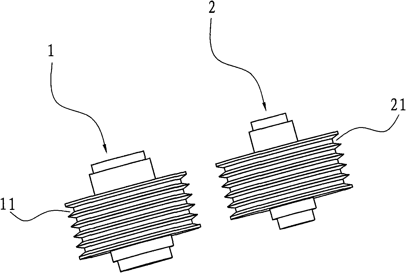
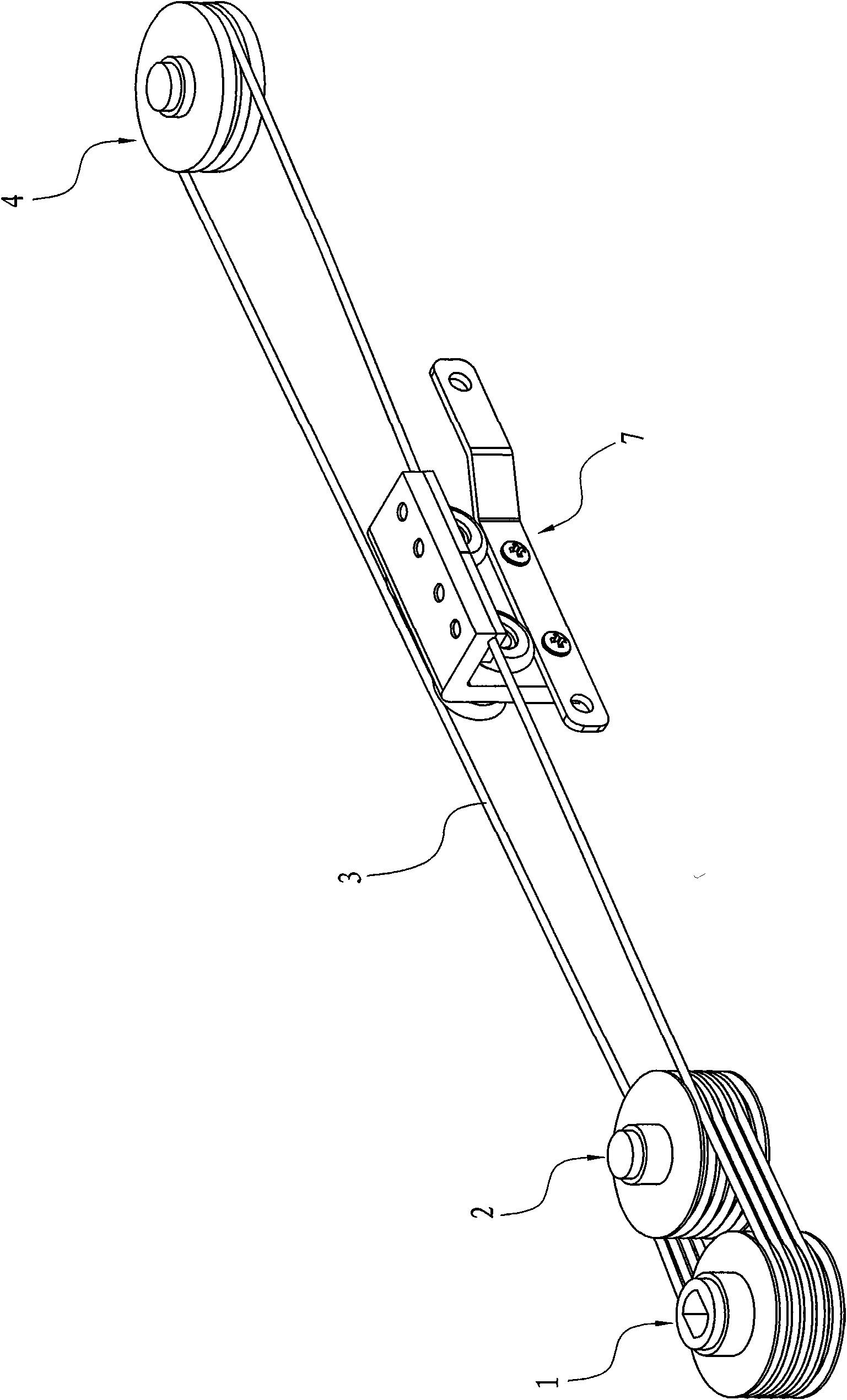
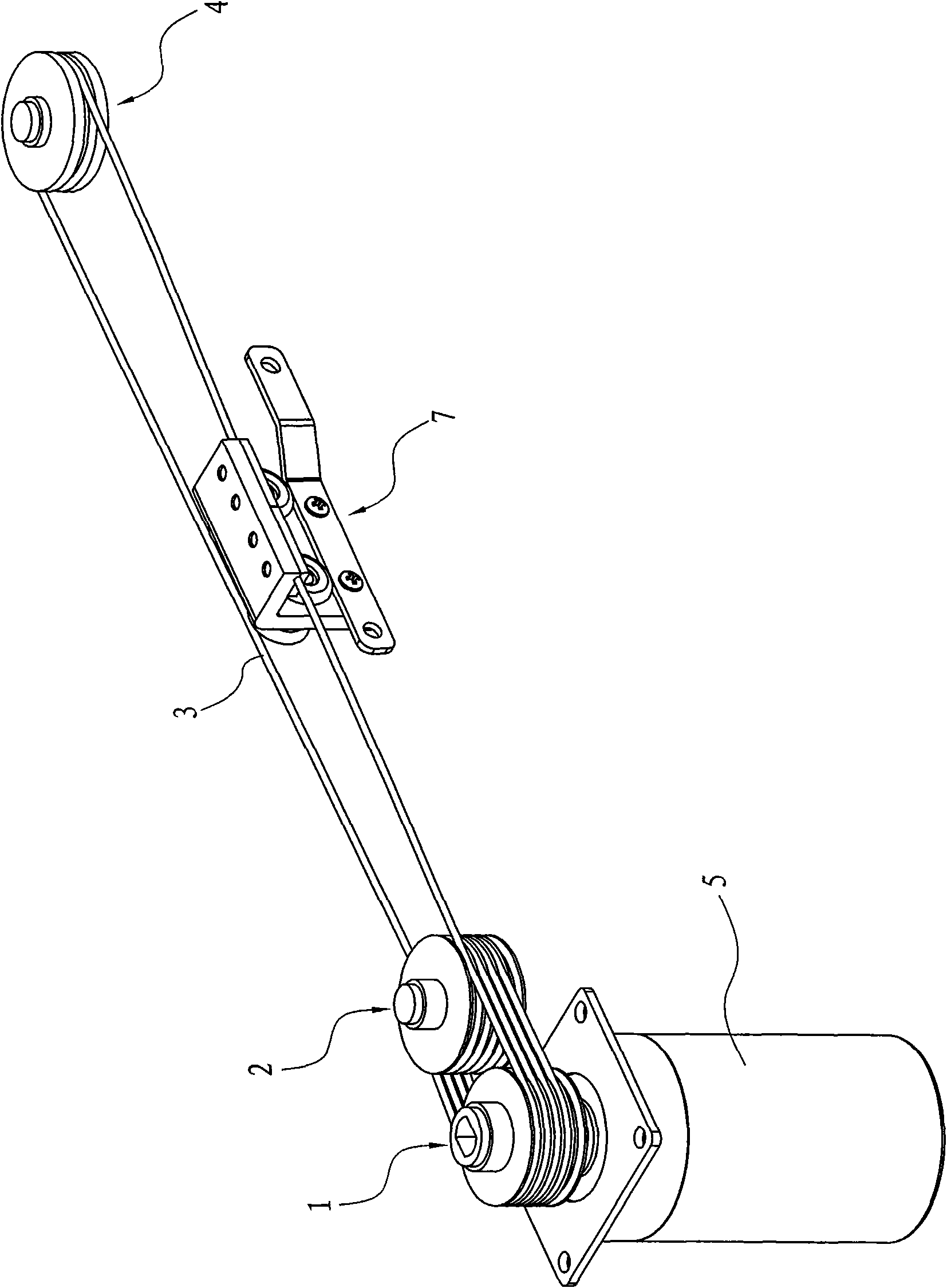
[0057] like figure 1 and 2 The rope traction mechanism shown uses the rope as the traction power to drive the external load to move, and it includes a first tension pulley 1, a second tension pulley 2, a rope 3, and a steering pulley 4, wherein the first tension pulley 1 The outer peripheral wall is provided with five annular grooves 11 arranged at intervals, and the outer peripheral wall of the second tensioning wheel 2 is also provided with five annular grooves 21 arranged at intervals; and the first tensioning wheel 1 and the second tensioning wheel 2 Adjacent to each other and arranged side by side at intervals and the two shafts are parallel; and the steering wheel 4 is set away from the first tensioning pulley 1 and the second tensioning pulley 2; The steering pulley 4 comes and walks around the first annular groove of the first tension pulley 1 in the direction close to the first tension pulley 1, and then moves away from the first tension pulley 1 and close to the se...

Embodiment 2

[0066] Different from Embodiment 1, the present invention also includes at least one guide wheel 9, and the guide wheel 9 is also set away from the two tension pulleys. The rope section between is used to connect the external load traction frame 7 of the external connection, and the rope section between the guide wheel 9 and the second tensioning wheel 2 is also used to connect the external load traction frame of the external connection, see Figure 6 shown. In this way, the movement direction of the external load can be adjusted freely.

Embodiment 3

[0068] Different from Embodiment 1, the number of turns of the rope on the first tensioning pulley and the second tensioning pulley is 1 turn or between 1 turn and 2 turns, such as 1.5 turns. And the annular groove on the outer peripheral wall of the second tensioning wheel can have only one, also can be multiple, but the rope is only wound once on the second tensioning wheel, and its specific winding method is: the rope enters the first tensioning wheel The wire inlet comes from the steering pulley and walks around the first annular groove of the first tension pulley in the direction close to the first tension pulley, and then moves away from the first tension pulley and close to the second tension pulley. Go around the annular groove on the second tensioning wheel in the direction of the second tensioning wheel, and then go around the second annular groove of the first tensioning wheel in a direction away from the second tensioning wheel and close to the first tensioning whee...


PUM


Abstract

The invention relates to a rope traction mechanism and a push-pull window using the rope traction mechanism, wherein the rope traction mechanism comprises a first tensioning wheel and a second tensioning wheel, a steering wheel and a rope. The outer peripheral wall of each tensioning wheel is provided with at least two annular grooves which are spaced from each other. The two tensioning wheels areadjacent to and spaced from each other in the same row. Rotating shafts of the tensioning wheels are parallel to each other. At least one tensioning wheel is driven by an externally-connected power to rotate. The steering wheel is away from the first and the second tensioning wheels. The rope enters a wire inlet end of the first tensioning wheel, starts from the steering wheel, extends past the first annular groove of the first tensioning wheel in a direction adjacent to the first tensioning wheel, and then goes past the first annular groove of the second tensioning wheel and finally back tothe second annular groove of the first tensioning wheel, thereby forming a complete winding circle. The winding of the rope continues, and then at least one subsequent winding circle is formed. Finally, the rope comes out of a wire outlet end of the first or the second tensioning wheel and is wound back to the steering wheel to be from head-end connection with the wire inlet end.

Description

technical field [0001] The invention relates to a rope traction mechanism, in particular to a rope traction mechanism using a rope as traction power, and a sliding window using the rope traction mechanism. Background technique [0002] In human life and production, friction is everywhere. According to its nature, friction can be divided into three types: sliding friction, static friction and rolling friction. Among them, the sliding friction is equal to the multiplication of the dynamic friction coefficient and the normal pressure, that is [0003] f=u×N [0004] Among them, u is the coefficient of dynamic friction, and N is the normal pressure; the coefficient of dynamic friction is determined by the roughness of the contact surface between two objects with interaction friction. [0005] Mechanics tells us that when a rope wrapped around a pile slides, the friction can reach an extreme degree. The more turns of the rope, the greater the friction. The law of friction fo...

Claims


Application Information

Patent Timeline
IPC IPC(8): E05F11/06E05F15/14E06B3/46E05D13/00F16H7/04F16H7/08E05F15/643
Inventor 瞿德阳
Owner 瞿德阳
Why Eureka
Try Eureka