Vacuum steam recovery device for steam turbine

A recovery device and steam turbine technology, which is applied in the direction of steam engine equipment, steam recovery, mechanical equipment, etc., can solve the problems that the latent heat of the exhaust steam of the steam turbine cannot be utilized, the pressure difference of the steam turbine is increased, and water resources are wasted, so as to achieve a large suction force and reduce Small power consumption, the effect of improving quality

Inactive Publication Date: 2013-02-13
李树生
View PDF0 Cites 0 Cited by
  • Summary
  • Abstract
  • Description
  • Claims
  • Application Information

AI Technical Summary

Problems solved by technology

This technology of increasing the pressure difference of the steam turbine wastes a lot of water resources, and the latent heat of the exhaust steam of the steam turbine cannot be utilized, wasting a lot of heat energy

Method used


Image

  • Vacuum steam recovery device for steam turbine

Examples


Embodiment Construction

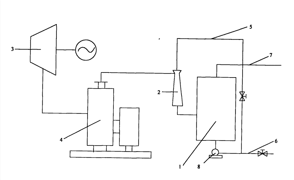
[0016] see figure 1 , a steam turbine vacuum steam recovery device, including a steam turbine 3, a closed exhaust steam recovery tank 1 and a jet pump 2, the jet pump is installed vertically, and a high pressure pump 8 is connected to the bottom of the closed exhaust steam recovery tank , the outlet of the high-pressure pump is connected to the jet pipeline 5, the jet outlet of the jet pump is connected to the inlet of the closed exhaust steam recovery tank, the jet inlet is connected to the outlet of the jet pipeline, and the suction inlet is connected to the steam turbine through the fan 4 The exhaust steam outlet, the closed exhaust steam recovery tank maintains a pressure sufficient to convert at least part of the exhaust steam into liquid water.

[0017] The length of the jet pump is not less than 3 meters. The height drop of the jet pump itself can increase the jet velocity and jet pressure, thereby enhancing the suction such as the suction force at the mouth.

[0018]...


PUM


Abstract

The invention relates to a vacuum steam recovery device for a steam turbine, comprising a closed dead steam recovery tank and an efficient jet pump, wherein, the efficient jet pump is arranged in a vertical manner, and the bottom of the closed dead steam recovery tank is connected with a high pressure pump; an outlet of the high pressure pump is connected with a jet pipeline; a jet outlet of the efficient jet pump is connected with an inlet of the closed dead steam recovery tank, and a jet inlet is connected with an outlet of the jet pipe; and a suction inlet is connected with a dead steam outlet of the steam turbine by a fan, and the closed dead steam recovery tank maintains enough pressure which can transform at least part of dead steam into liquid water. The device assures differentialpressure of the steam turbine, and meanwhile recovers the dead steam of the steam turbine with pressure difference generated by each equipment and self drop height of the efficient jet pump as power,thus effectively utilizing heat energy in the dead steam, and avoiding thermal pollution; and the device can be mainly applied to various occasions provided with the steam turbine.

Description

technical field [0001] The invention relates to a steam turbine vacuum steam recovery device, which is mainly used in various occasions with steam turbines. Background technique [0002] In order to maximize the work, the end of the existing steam turbine is equipped with a condenser and various forms of cooling towers to cool the exhaust steam at the end of the steam turbine, turning it into condensed water and discharging it to greatly reduce Small volume, forming a negative pressure at the end of the steam turbine to greatly increase the pressure difference between the front and back of the steam turbine. This technology of increasing the pressure difference of the steam turbine wastes a lot of water resources, and the latent heat of the exhaust steam of the steam turbine cannot be utilized, wasting a lot of heat energy. Contents of the invention [0003] In order to overcome the above-mentioned defects of the prior art, the present invention provides a steam turbine v...

Claims


Application Information

Patent Timeline
Patent Type & Authority Patents(China)
IPC IPC(8): F01K19/08
Inventor 李树生
Owner 李树生
Why Eureka
Try Eureka