Exhaust device of rotary compressor

A rotary compressor and exhaust device technology, applied in the field of refrigeration compressors, can solve the problems of small number of exhaust devices, large exhaust resistance, large clearance volume of exhaust devices, etc., to reduce clearance volume and improve efficiency , to avoid the effect of mechanical noise

Active Publication Date: 2010-02-10
GREE ELECTRIC APPLIANCES INC +1
View PDF0 Cites 9 Cited by
  • Summary
  • Abstract
  • Description
  • Claims
  • Application Information

AI Technical Summary

Problems solved by technology

[0004] The purpose of the present invention is to provide a rotary compressor that can solve the above problems in view of the problems that the clearance volume of the exhaust device of the rotary compressor is too large, the noise is relatively large, and the number of exhaust devices is too small, resulting in excessive exhaust resistance. machine exhaust

Method used


Image

  • Exhaust device of rotary compressor
  • Exhaust device of rotary compressor
  • Exhaust device of rotary compressor

Examples


Embodiment 1

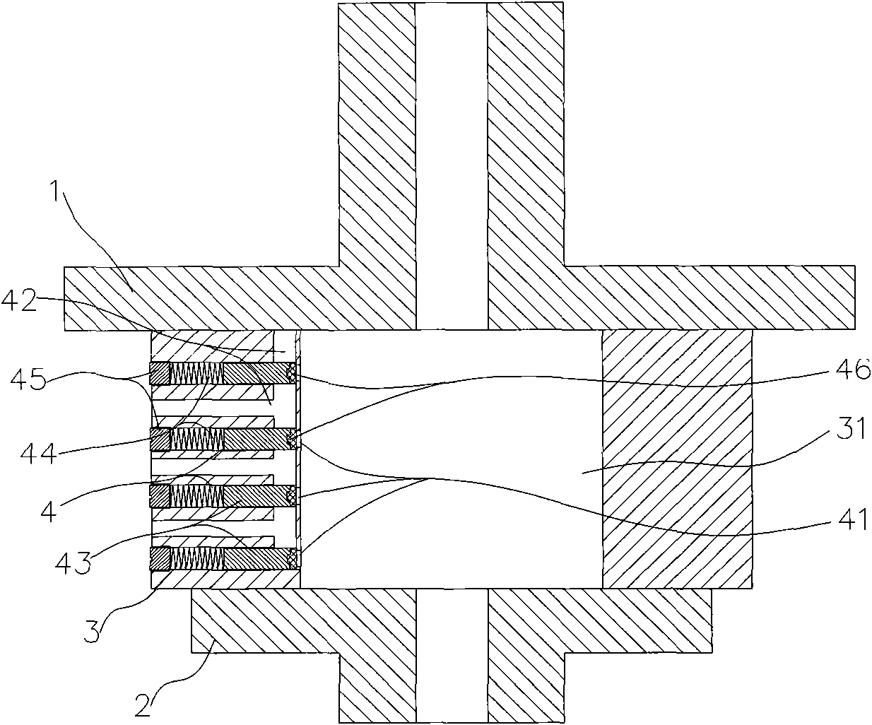
[0019] A rotary compressor exhaust device such as figure 2 As shown, the upper flange 1 and the lower flange 2 of the rotary compressor are arranged at both ends of the cylinder 3 to enclose a sealed cylinder cavity 31. At the exhaust position, a horizontal half-open piston is arranged on the cylinder wall of the cylinder 3. Channel 4, the opening of the piston channel 4 is located at the outer end of the cylinder 3, the bottom is adjacent to the cylinder cavity 31, and the bottom is provided with an exhaust port 41 connected to the cylinder cavity 31, and an upper flange 1 is arranged axially on the cylinder wall The flow path is connected to the bottom of the piston passage 4, thus forming the exhaust passage 42 of the exhaust device; a piston 43 is slidably arranged in the piston passage 4, and a thrust spring 44 is arranged at the outer end of the piston 43, and the thrust spring 44 Outer end is provided with supporting device 45, and supporting device 45 is a blockage be...

Embodiment 2

[0021] A rotary compressor exhaust device such as image 3 As shown, the upper flange 1 and the lower flange 2 of the rotary compressor are arranged at both ends of the cylinder 3 to enclose a sealed cylinder cavity 31. At the exhaust position, four transverse semi-open pistons are arranged on the cylinder wall of the cylinder 3. Channel 4, the opening of the piston channel 4 is located at the outer end of the cylinder 3, the bottom is adjacent to the cylinder cavity 31, the bottom is provided with an exhaust port 41 connected to the cylinder cavity 31, and a cylinder wall is axially provided with a hole extending through each piston. The flow channel at the bottom of the channel 4, the cylinder 3 is horizontally provided with a flow channel connecting the flow channel and the outside of the cylinder chamber 31, and the axial flow channel and the lateral flow channel form the exhaust channel 42 of the exhaust device; each piston channel 4 A piston 43 is slidingly arranged in t...

Embodiment 3

[0023] A rotary compressor exhaust device such as Figure 4 As shown, the upper flange 1 and the lower flange 2 of the rotary compressor are arranged at both ends of the cylinder 3 to enclose a sealed cylinder cavity 31. At the exhaust position, four transverse semi-open pistons are arranged on the cylinder wall of the cylinder 3. Channel 4, the opening of the piston channel 4 is at the outer end of the cylinder 3, the bottom is adjacent to the cylinder chamber 31, the bottom is provided with an exhaust port 41 connected to the cylinder chamber 31, and a cylinder wall is axially provided with a channel connecting each piston. 4 and runs through the upper flange 1 and the lower flange 2 flow passages, through which the upper flange 1 and lower flange 2 are connected to the flow passages outside the cylinder chamber 31 to form an exhaust passage 42; each piston passage 4 is slidingly set A piston 43, the outer end of the piston 43 is provided with a thrust spring 44, and the out...


PUM


Abstract

The invention relates to the technical field of refrigeration compressors, in particular to an exhaust device of a rotary compressor; in the exhaust device of the rotary compressor, a piston channel is arranged on a wall of an air cylinder, the bottom part of the air cylinder is provided with an exhaust port communicated with an air cylinder cavity, the inner end of a piston is tightly close to and blocks the exhaust port under the action of spring thrust; when the compressor exhausts air in the working process, the piston slides outwards in a piston channel, so as to remove blocking to the exhaust port, at the moment, high-pressure air in the air cylinder cavity is exhausted outside a compressing cavity through the exhaust port and an exhaust pipeline; the exhaust device in the inventioncan reduce clearance volume of the compressor in the exhaust process, and the efficiency of the compressor is improved; the mechanical noise generated by repeat beating is avoided when the traditionalcompressor is exhausted; in addition, a plurality of exhaust devices are arranged on the air cylinder wall according to needs, so as to bear the exhaust pressure respectively, reduce the exhaust resistance and reduce energy loss.

Description

technical field [0001] The invention relates to the technical field of refrigeration compressors, in particular to a rotary compressor exhaust device. Background technique [0002] The compressor is the core equipment for compressing the refrigerant in the refrigerator and air-conditioning system to make it participate in the cycle. The rotary compressor is a commonly used compressor. The rotary compressor generally includes a rotary compressor and a swing compressor. The work is completed in the sealed cylinder chamber of the compressor. The upper flange and the lower flange are arranged at both ends of the cylinder to form a sealed cylinder chamber. The compression of the gas is carried out in the cylinder chamber. The compressed gas in the cylinder chamber is properly When the high pressure is discharged from the cylinder chamber through the exhaust device. [0003] The exhaust device of the prior art rotary compressor (see figure 1 ) Usually, the upper and lower flange...

Claims


Application Information

Patent Timeline
Patent Type & Authority Applications(China)
IPC IPC(8): F04C29/12
Inventor 王勇李建民
Owner GREE ELECTRIC APPLIANCES INC
Why Eureka
Try Eureka