Dispatching method of annular propulsion timer

A scheduling method and timer technology, applied in the direction of program startup/switching, multi-program device, electrical components, etc., can solve problems such as speed blocks, and achieve the effects of improved scanning efficiency, improved efficiency, and fast positioning

Active Publication Date: 2010-02-10
无锡威泰迅电力科技有限公司
View PDF0 Cites 10 Cited by
  • Summary
  • Abstract
  • Description
  • Claims
  • Application Information

AI Technical Summary

Problems solved by technology

[0010] The above-described timer scheduling method, when scheduling a large number of timers (such as tens of thousands), usually cannot simultaneously address the following issues: 1, the scanning efficiency of the timer; 2, the deletion and addition efficiency of the timer; 3, the ti

Method used


Image

  • Dispatching method of annular propulsion timer
  • Dispatching method of annular propulsion timer
  • Dispatching method of annular propulsion timer

Examples


Embodiment Construction

[0029] The present invention will be further described below in conjunction with drawings and embodiments.

[0030] The ring-propelled timer scheduling method of the present invention is established on the basis of the above-mentioned classified timer scheduling method by introducing ring queues and global variables. The present invention comprises the steps:

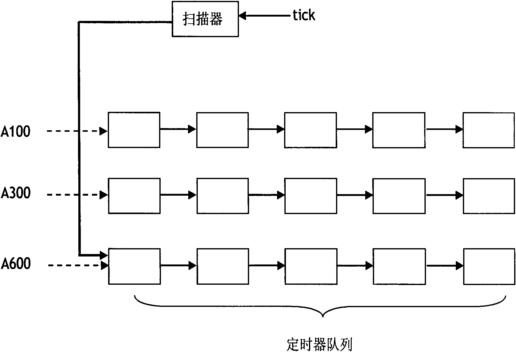
[0031] 1. According to the needs of the system, take an integer m and determine to establish W=2 m The head pointer of a timer queue, build a ring queue, the queue is as follows Figure 4 As shown, W timer linked lists are included, and these timer linked lists form a circular queue according to the number of remaining ticks, connected end to end.

[0032] 2. Create a global tickcount variable and initialize it to 0, which is used to point to the timer queue that may have a timeout;

[0033] 3. When adding a timer, do the MOD operation according to the delay and W to get N, and add this timer to the end of the Nth qu...


PUM


Abstract

The invention relates to a dispatching method of a timer, in particular to a dispatching method of an annular propulsion timer which carries out real-time communication protocol conversion, data collection and calculation in a secondary real-time monitoring device of an electric system. According to the requirements of the system, the dispatching method comprises the following steps: collecting anintegral number; ensuring and establishing head pointers of W=2<m> timer queues; establishing an annular queue; establishing a global tickcount variable with initialization as 0; and scanning, addingand deleting the timer by the tickcount variable, and the like. The dispatching method uses space to exchange time, greatly increases the scanning efficiency by establishing W+1 global variables andcircularly propelling the tickcount simultaneously and can quickly position through the tickcount because a large number of timers are dispersed in the W queues, thereby obviously increasing the adding and deleting efficiency.

Description

technical field [0001] The invention relates to a scheduling method of a timer, in particular to a scheduling method of a timer in which real-time communication protocol conversion, data collection and calculation are carried out circularly in a power system secondary real-time monitoring device. Background technique [0002] In the application of digital substations and digital grids, a large number of secondary side devices and equipment are required. These smart devices need to communicate with other smart devices in this compartment, smart devices in adjacent compartments, and upper and lower smart devices and systems. Exchanges, the protocols of these exchanges may be the same or different; at the same time, smart devices themselves need to perform high-density data collection and computing tasks. The start and completion of these tasks depend on the start, stop, query and other operations of the timer, and the efficiency of these operations of the timer seriously affec...

Claims


Application Information

Patent Timeline
IPC IPC(8): G06F9/48H02J13/00
Inventor 凌万水
Owner 无锡威泰迅电力科技有限公司
Why Eureka
Try Eureka