Flash memory equipment, method and system for managing flash memory

A flash memory management and flash memory technology, applied in the field of semiconductor storage media, can solve the problem of low available capacity of flash memory, and achieve the effect of increasing the available capacity

Active Publication Date: 2010-02-10
NETAK TECH KO LTD
5 Cites 12 Cited by

AI-Extracted Technical Summary

Problems solved by technology

[0007] One of the objects of the present invention is to provide a flash memory device, flash memory manageme...

Method used

In the present invention, by extracting the good block bound with bad block in the physical block binding table, set up fragmentary ...

Abstract

The invention provides flash memory equipment, a method and a system for managing a flash memory, which relate to the filed of semiconductor memory media. The method comprises the following steps: A,recording and configuring information according to the quality of a physical block of the flash memory, and establishing a binding table of the physical block and a recording table of a fragmentary block; and B, accessing the flash memory based on the binding table of the physical block and the recording table of the fragmentary block. The invention also provides the system for managing the flashmemory, which comprises a host computer, a control unit and the flash memory, wherein the host computer and the control unit are connected and perform data interaction; the control unit is used for accessing and controlling the flash memory; the host computer records and configures the information according to the quality of the physical block of the flash memory, and establishes the binding tableof the physical block and the recording table of the fragmentary block; and the control unit accesses the flash memory based on the binding table of the physical block and the recording table of thefragmentary block. The invention also provides the flash memory equipment. The adoption of the flash memory equipment, the method and the system for managing the flash memory can improve the availablecapacity of the flash memory.

Application Domain

Memory adressing/allocation/relocationRead-only memories

Technology Topic

Semiconductor memorySemiconductor +3

Image

  • Flash memory equipment, method and system for managing flash memory
  • Flash memory equipment, method and system for managing flash memory
  • Flash memory equipment, method and system for managing flash memory

Examples

  • Experimental program(1)

Example Embodiment

[0037] In the present invention, by extracting the good blocks bound to the bad blocks in the physical block binding table, a fragmented block record table is established to achieve access to the good blocks bound to the bad blocks, thereby increasing the available capacity of the flash memory.
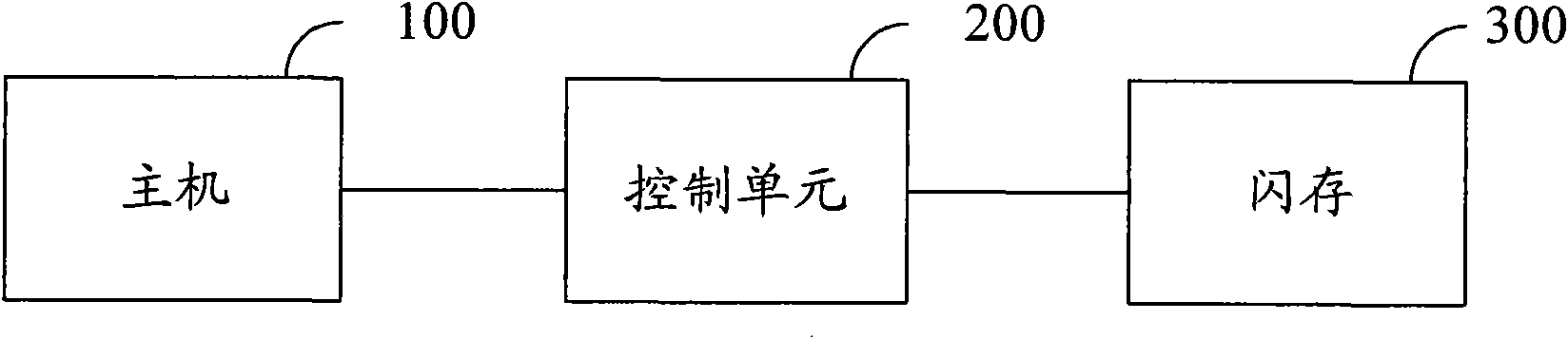
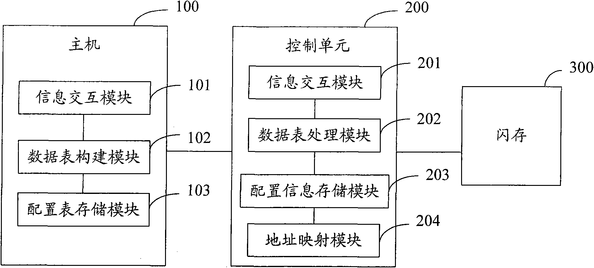
[0038] figure 2 The structure of a flash memory management system in an embodiment of the present invention is shown. The system includes a host 100, a control unit 200, and a flash memory 300. It should be noted that the connection relationship between the devices in all the diagrams of the present invention is to clearly explain the needs of their information interaction and control process, and therefore should be regarded as a logical connection relationship, and should not be limited to a physical connection. In addition, it should be noted that the communication modes between the functional modules can be multiple, and the protection scope of the present invention should not be limited to a specific type of communication mode. among them:
[0039] The host 100 is connected to the control unit 200 and performs data exchange, and is used to establish a physical block binding table and a fragmented block record table according to the physical block quality record and configuration information of the flash memory 300. It is typically a personal computer.
[0040] The control unit 200 is connected to the host 100 and performs data interaction, and accesses and controls the flash memory 300, for accessing the flash memory 300 based on the physical block binding table and the fragmented block record table. It is typically a microcontroller or microcontroller.
[0041] The flash memory 300 is connected to the host 100 and the control unit 200 and performs data interaction, and can be used to store a physical block binding table and a fragmented block record table.
[0042] image 3 The internal structure of a flash memory management system in an embodiment of the present invention is shown. The system includes a host 100, a control unit 200, and a flash memory 300. The host 100 includes an information exchange module 101, a data table construction module 102, and a configuration table storage module 103, where:
[0043] The information interaction module 101 is connected to the data table construction module 102 and the configuration table storage module 103 and performs data interaction, and is used to send scan instructions and configuration information of the flash memory 300 to the control unit 200, and receive physical block quality records fed back by the control unit 200 .
[0044] The data table construction module 102 is connected to the information exchange module 101 and the configuration table storage module 103 and performs data exchange, and is used to establish a physical block binding table and a fragmented block record table according to physical block quality records and configuration information. Figure 4 The internal structure of the data table construction module 102 in an embodiment of the present invention is shown, which includes a physical block binding table generation module 1021 and a fragmented block record table generation module 1022, wherein:
[0045] The physical block binding table generation module 1021 is connected to the fragmented block record table generation module 1022 and performs data exchange, and is used to bind corresponding physical blocks in different areas according to the configuration information of the flash memory 300 to establish a physical block binding table.
[0046] The fragmented block record table generating module 1022 is connected to the physical block binding table generating module 1021 and performs data interaction, and is used to extract the binding quality of the bad block in the physical block binding table according to the physical block quality record of the flash memory, and establish Fragmentary block record table.
[0047] The configuration table storage module 103 is connected to the information interaction module 101 and the data table construction module 102 to perform data interaction, and is used to store configuration information tables of various flash memories. The configuration information table records configuration information of various flash memories. In an embodiment, the configuration information table is shown in Table 1:
[0048] Flash type
[0049] Table 1
[0050] The control unit 200 includes an information interaction module 201, a data table processing module 202, a configuration information storage module 203, and an address mapping module 204, among which:
[0051] The information interaction module 201 is connected to the data table processing module 202, the configuration information storage module 203, and the address mapping module 204 and performs data interaction for receiving scan instructions and configuration information, scanning the flash memory 300, and obtaining physical block quality records.
[0052] The data table processing module 202 is connected to the information exchange module 201, the configuration information storage module 203, and the address mapping module 204 and performs data exchange, and is used to number the binding blocks in the physical block binding table and to record the fragmented blocks in the table The number of fragments. In a preferred embodiment, the data table processing module 202 sequentially numbers the binding blocks in the physical block binding table.
[0053] There are two ways to number the fragmented binding blocks. In an embodiment, the number of the binding block containing the bad block in the physical block binding table is used as the number of the fragmented block. In another embodiment, the fragmented blocks are sequentially numbered after the number of the bound block in the physical block binding table.
[0054] The configuration information storage module 203 is connected to the information interaction module 201, the data table processing module 202, and the address mapping module 204 to perform data interaction, and is used to store the configuration information of the flash memory 300.
[0055] The address mapping module 204 is connected to the information interaction module 201, the data table processing module 202, and the configuration information storage module 203 and performs data interaction, and is used to establish a mapping relationship between a logical address and a physical address.
[0056] The flash memory 300 is connected to the host 100 and the control unit 200 and performs data interaction, and is used to store a physical block binding table and a fragmented block record table.
[0057] In an embodiment, the control unit 200 may be connected to an external memory for storing the physical block binding table and the fragmented block record table.
[0058] Figure 5 A flash memory device in an embodiment of the present invention is shown, and the flash memory device includes a controller 10 and a flash medium 20. When the flash memory device intervenes in the host 100, the controller 10 accesses the flash media 20 based on the physical block binding table and the fragmented block record table established by the host 100. In an implementation example, a good block bound to a bad block in the physical block binding table is recorded in the fragmented block record table.
[0059] Image 6 The method flow of flash memory management in an embodiment of the present invention is shown, and the method flow is based on figure 2 The system structure shown, the specific process is as follows:
[0060] In step S601, the host 100 establishes a physical block binding table and a fragmented block record table according to the physical block quality record and configuration information of the flash memory 300.
[0061] In step S602, the control unit 200 accesses the flash memory 300 based on the physical block binding table and the fragmented block record table.
[0062] Figure 7 The method flow of flash memory management in an embodiment of the present invention is shown, and the method flow is based on image 3 The system structure shown, the specific process is as follows:
[0063] In step S701, the control unit 200 scans the flash memory 300 to obtain a record of the physical blocks of the flash memory 300. In an embodiment, the specific process of step S701 is: (1) When the flash memory 300 is connected to the control unit 200, the information interaction module 201 reads the ID number of the flash memory 300 and feeds it back to the host 100, and the host 100 uses the ID of the flash memory 300 Search for the configuration information of the flash memory 300 from the configuration information table stored in the configuration table storage module 103. For example, if the ID number of the flash memory 300 is 123456789, the configuration information of the flash memory 300 is found to be type 1 in Table 1; (2) The information interaction module 101 of the host 100 sends a scan instruction and configuration information of the flash memory 300 to the control unit 200, and the information interaction module 201 of the control unit 200 receives the scan instruction and starts scanning the flash memory 300 to obtain physical block quality records; (3) Information interaction module The configuration information received by 201 is stored in the configuration information storage module 203, and the control unit 200 can access and control the flash memory 300 according to the configuration information.
[0064] In step S702, the host 100 establishes a physical block binding table according to the configuration information of the flash memory 300. In one embodiment, the specific process of step S702 is: after the control unit 200 obtains the physical block quality record, the information interaction module 201 feeds back the physical block quality record to the host 100, and the data table construction module 102 according to the configuration information of the flash memory 300 , Establish a physical block binding table. In an embodiment, the physical block binding table generation module 1021 binds corresponding physical blocks in different areas according to the configuration information of the flash memory 300 to establish a physical block binding table. In an example solution, the configuration information of the flash memory 300 is shown in Table 2:
[0065] How many physical blocks does each flash have
[0066] Table 2
[0067] It can be seen from Table 2 that taking the 2Plane technology as an example, the flash memory 300 has 2 planes, and each plane has a difference of 1 block, that is, the even-numbered block is one plane, and the odd-numbered block is another plane. The physical blocks must be located in different regions. Therefore, when binding, block 0 and block 1 are bound, block 2 and block 3 are bound... and so on, to obtain the physical block binding table shown in Table 3.
[0068] Zone 1
[0069] table 3
[0070] It should be noted that the foregoing Table 2 and Table 3 are only used to illustrate the establishment process of the physical block binding table, and the configuration information and the physical block binding table are not limited to the table form in Table 2 and Table 3.
[0071] In step S703, the host 100 extracts the good blocks bound to the bad in the physical block binding table according to the physical block good and bad records, and establishes a fragmented block record table. In one embodiment, the fragment record table generating module 1022 extracts the binding quality of the bad block in the physical block binding table, and establishes the fragment record table. For example, as shown in the physical block binding table shown in Table 3, suppose that block 79, block 100, block 203, and block 796 are bad blocks, and the good or bad bound to them are block 78, block 101, block 202, and block 797, respectively. The fragmented block record table generation module 1022 extracts block 78, block 101, block 202, and block 797, and establishes a fragmented block record table. You can use data or linked lists to record fragmented blocks. In an embodiment, the fragmented block record table generation module 1022 uses the following array to record fragmented blocks (ie, block 78, block 101, block 202, and block 797):
[0072] WORD sheet[1000];
[0073] Sheet[0]=78;
[0074] Sheet[1]=101;
[0075] Sheet[2]=202;
[0076] Sheet[3]=797.
[0077] The established physical block binding table and fragmented block record table may be stored in the flash memory 300, or may be stored in an external memory connected to the control unit 200.
[0078] In step S703, the control unit 200 accesses the flash memory 300 based on the physical block binding table and the fragmented block record table.
[0079] Figure 8 The flow of a method for the control unit 200 to access the flash memory 300 in an embodiment of the present invention is shown, and the specific process is as follows:
[0080] In step S801, the data table processing module 202 numbers the binding blocks in the physical block binding table, obtains the address boundaries of the binding blocks, and numbers the fragmented blocks in the fragmented block recording table. In a preferred embodiment, the specific process of step S801 is: the data table processing module 202 sequentially number the binding blocks in the physical block binding table, for example, to bind the binding blocks in the physical block binding table shown in Table 3. The sequence number of fixed blocks is: the block after block 0 and block 1 are bound as binding block 0, the block after block 2 and block 3 are bound as binding block 1...and so on, then The last binding block is binding block 4095. The data table processing module 202 binds the fragmented blocks in the fragmented block record table, such as the fragmented blocks recorded in the above-mentioned array, wherein the block 78 is bound with the block 101, and the block 202 is bound with the block 797.
[0081] There are two ways to number the fragmented binding blocks. In one embodiment, the number of the binding block containing the bad block in the physical block binding table is used as the number of the fragmented block. As shown in the physical block binding table in Table 3, it is assumed that block 79, block 100, block 203 and Block 796 is a bad block, then the binding blocks that bind these bad blocks are binding block 39, binding block 50, binding block 101, and binding block 398. The number of fragmented blocks is: block 78 and block 101 as A fragmented binding block is denoted as block 39, and block 202 and block 797 are denoted as a fragmentary binding block as block 50.
[0082] In another embodiment, the fragmented blocks are sequentially numbered after the number of the binding block in the physical block binding table, such as the physical block binding table shown in Table 3, all physical blocks are bound after being bound. Blocks 0 to 4095, the number of fragmented blocks is: block 78 and block 101 are recorded as block 4096 as a fragmented binding block, and block 202 and block 797 are recorded as block 4097 as a fragmented binding block. The process of accessing the flash memory 300 of the present invention will be described in detail below by taking the sequential numbering of the fragmented blocks as an embodiment.
[0083] In step S802, the address mapping module 204 establishes a mapping relationship between a logical address and a physical address, and obtains the address of the sector to be accessed. The access process of the flash memory 300 will be described in detail below by taking the access sector 4194316 as an example.
[0084] In step S803, according to the configuration information of the flash memory 300, the address of the binding block to be accessed and the sector address in the binding block are calculated. In one embodiment, the configuration information of the flash memory 300 is shown in Table 2. According to the configuration information, the flash memory 300 has 8192 physical blocks, each physical block has 128 pages, and each physical page has 4 sectors. A binding block is composed of two physical blocks, and sector 4194316 is the 12th sector of the binding block 4096.
[0085] In step S804, it is determined whether the address of the binding block to be accessed is smaller than the address boundary of the binding block. If yes, go to step S806, otherwise go to step S805. In this embodiment, the binding block to be accessed is the binding block 4096, and according to the physical block binding table shown in Table 2, the last binding block is the binding block 4095, which is the address boundary of the binding block It is 4096. Then go to step S805.
[0086] In step S805, the control unit 200 accesses the physical block through the original read and write command. In this embodiment, the process of step S805 is specifically as follows: since the above calculation has been calculated that the 12th sector in the binding block 4096 is to be accessed, and the largest binding block in the physical block binding table is the binding block 4095, the fragmented binding blocks are sequentially numbered after the binding block 4096. It can be seen from this that what needs to be accessed is actually the 12th sector of the fragmented binding block 4096. Since a physical block has 128 pages and each page has 4 sectors, the 12th sector of the binding block 4096 is actually The first physical block contained in block 4096 is physical block 78. The physical block 78 is accessed through the original read and write command, which is a command for individually accessing a physical block. The access to the flash memory by the original read and write command is an existing technology, which will not be repeated here.
[0087] If the address of the binding block to be accessed is smaller than the address boundary of the binding block, step S806 is entered.
[0088] In step S806, the control unit 200 accesses the physical block by binding accelerated read and write commands. In one embodiment, if the binding block to be accessed is smaller than the address boundary 4096, the accessed binding block is the binding block in the physical block binding table, and the physical block is processed through the binding accelerated read and write command. Access. The access to the flash memory by binding accelerated read and write commands is an existing technology, and will not be repeated here.
[0089] According to the flash memory standard, there may be 4% bad blocks. In the above-described embodiment, 327 of the 8192 physical blocks may be bad blocks. If the binding acceleration technology of the prior art is used, it will be compared with these 327 bad blocks. Good blocks bound by blocks are also marked as bad blocks and cannot be used. By adopting the present invention, the good blocks bound to 327 bad blocks can also be used. Taking the flash memory 300 in Table 2 as an example, one physical block is 256KB and 327 physical blocks are 83MB. With the present invention, the current The 83MB that cannot be used technically is also used, so the capacity of the flash memory 300 can be expanded up to 83MB.
[0090] The above are only the preferred embodiments of the present invention and are not intended to limit the present invention. Any modification, equivalent replacement and improvement made within the spirit and principle of the present invention shall be included in the protection of the present invention. Within range.

PUM

no PUM

Description & Claims & Application Information

We can also present the details of the Description, Claims and Application information to help users get a comprehensive understanding of the technical details of the patent, such as background art, summary of invention, brief description of drawings, description of embodiments, and other original content. On the other hand, users can also determine the specific scope of protection of the technology through the list of claims; as well as understand the changes in the life cycle of the technology with the presentation of the patent timeline. Login to view more.

Similar technology patents

Dynamically-reconfigurable battery energy storage system and method

InactiveCN107171387AImprove the ability to use informationIncrease usable capacity
Owner:STATE GRID SHANDONG ELECTRIC POWER +1

Packaging bag with planar bag opening or valve flat bottom

InactiveCN105035497AIncrease usable capacityimprove aesthetics
Owner:ZHONGSHAN NCA

Classification and recommendation of technical efficacy words

  • Increase usable capacity

Dynamically-reconfigurable battery energy storage system and method

InactiveCN107171387AImprove the ability to use informationIncrease usable capacity
Owner:STATE GRID SHANDONG ELECTRIC POWER +1

Packaging bag with planar bag opening or valve flat bottom

InactiveCN105035497AIncrease usable capacityimprove aesthetics
Owner:ZHONGSHAN NCA
Why Eureka
Try Eureka