Electric isolating switch

An isolation switch and electric technology, which is applied to the parts of the air switch, the power device inside the switch, etc., can solve the problems of unfavorable layout and installation of the electric isolation switch, large assembly and adjustment workload, and low transmission efficiency of the mechanism. The installation arrangement, the structure is simple, and the effect of improving the transmission efficiency of the mechanism

Active Publication Date: 2010-02-10
中国船舶重工集团公司第七一二研究所
View PDF0 Cites 6 Cited by
  • Summary
  • Abstract
  • Description
  • Claims
  • Application Information

AI Technical Summary

Problems solved by technology

Due to the use of a motor plus a multi-stage deceleration mechanism, its volume is large, the transmission efficiency of the mechanism is low, and the structure is complex, the workload of assembly and adjustment is large, and the cost is high; at the same time, due to the large size, it is not conducive to the installation of the electric isolating switch in the switch cabinet. layout and installation

Method used


Image

  • Electric isolating switch
  • Electric isolating switch
  • Electric isolating switch

Examples


Embodiment Construction

[0018] The present invention is further described as follows in conjunction with accompanying drawing and embodiment:

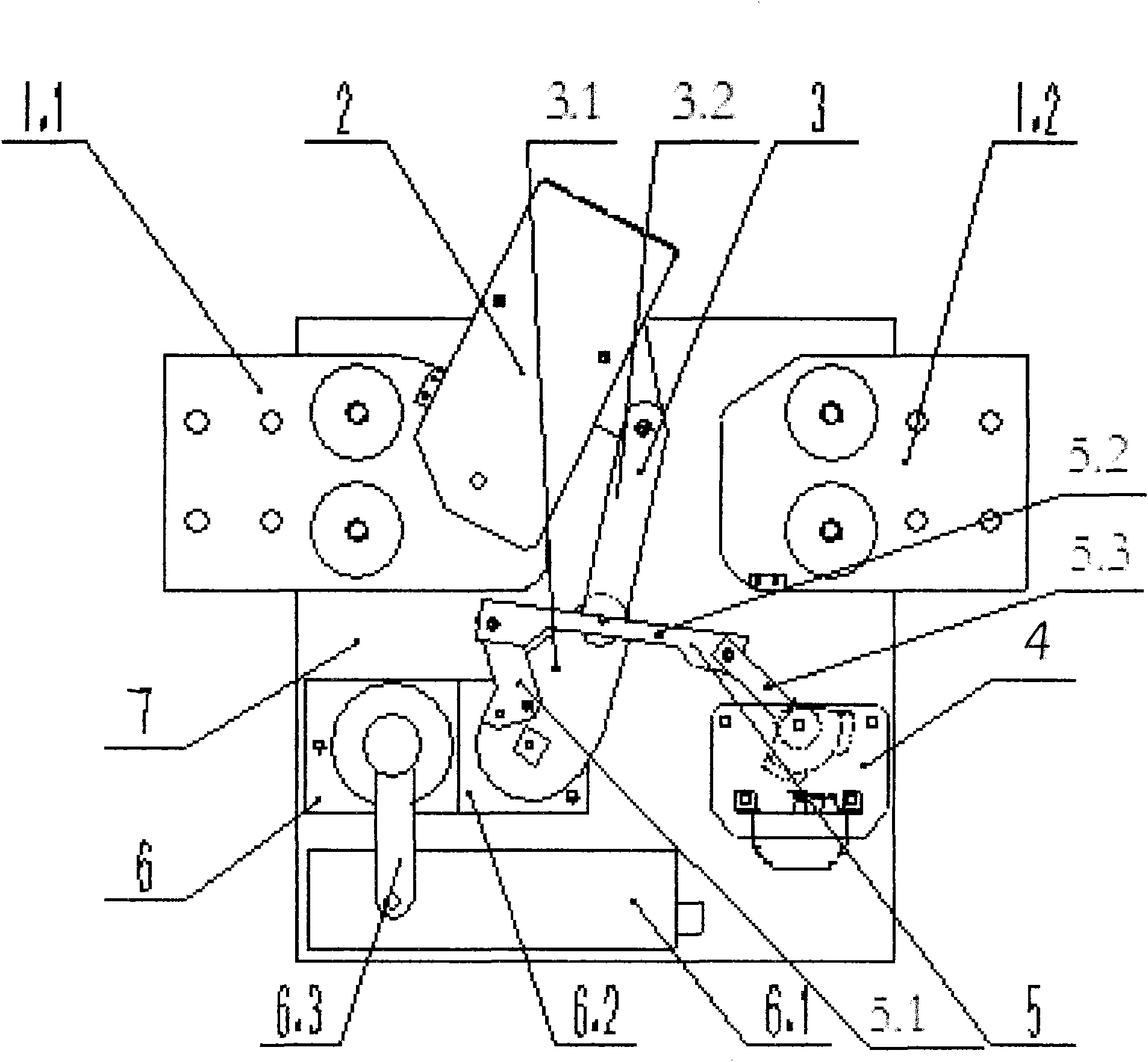
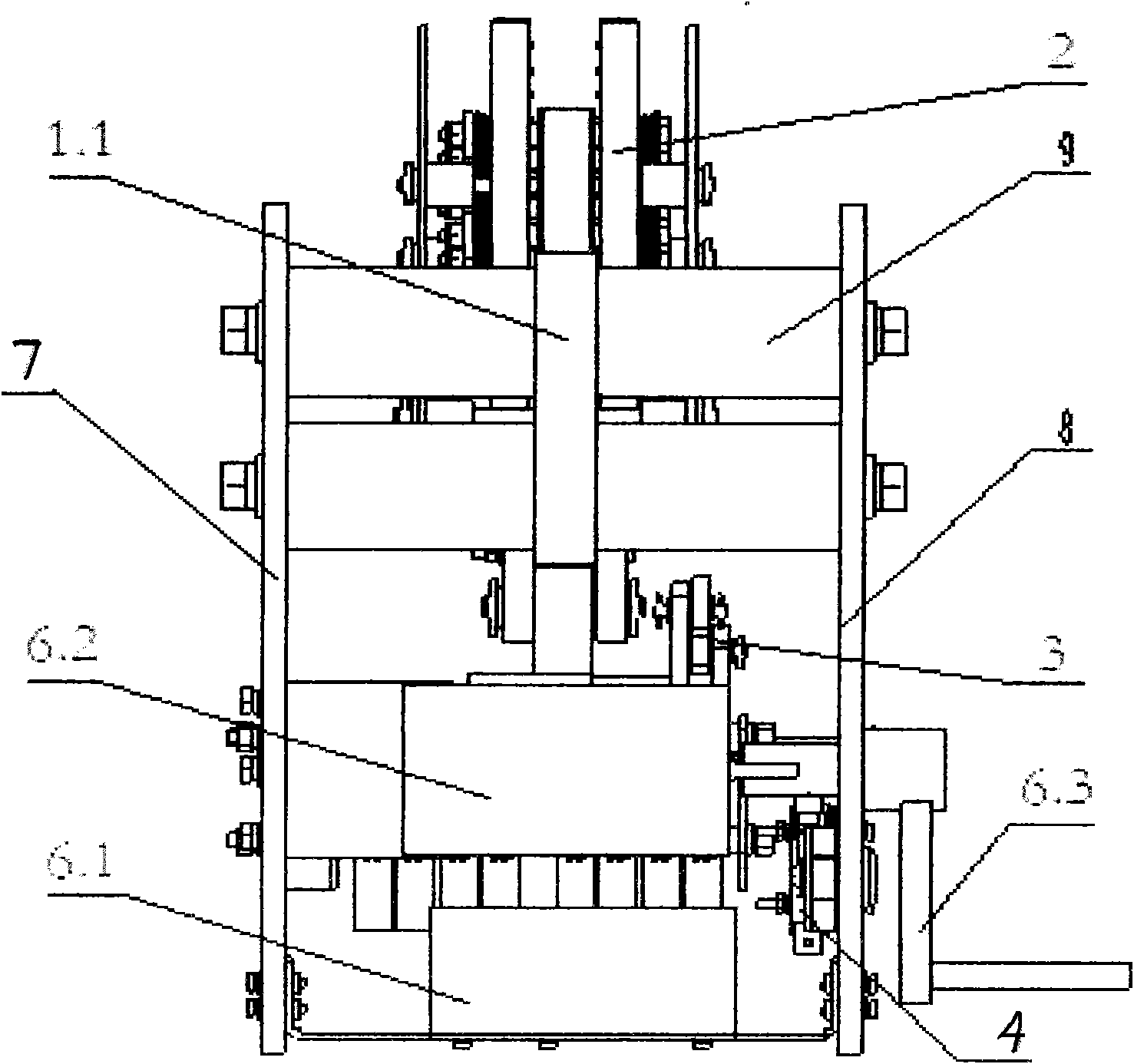
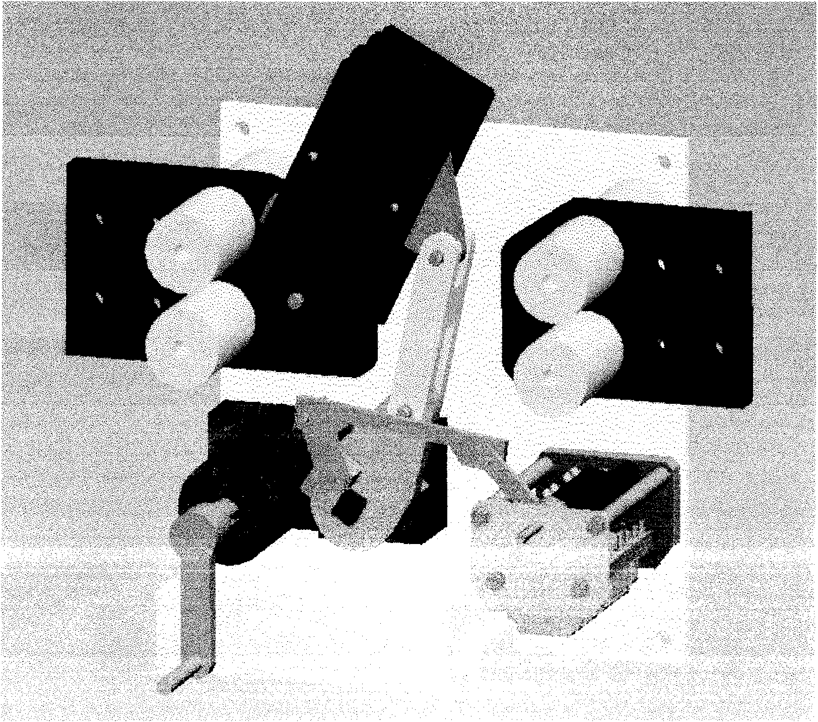
[0019] As shown in the figure: an electric isolating switch, connecting busbars 1.1 and 1.2 are installed between the front insulating plate 8 and the rear insulating plate 7, and contacts and contact control systems are also installed, including: moving contact group 2. The link mechanism 3 connected with the moving contact group 2, the operating system 6 that provides power and controls the opening and closing of the moving contact group 2, and the auxiliary switch assembly 4; the operating system 6 is a descending The voltage speed regulation system has a geared motor 6.2 and a switching power supply 6.1 that acts as a step-down speed regulator for the geared motor 6.2; the auxiliary switch assembly 4 is connected with the geared motor 6.2 through the auxiliary switch assembly transmission mechanism 5 and the linkage mechanism 3. The reduction motor 6.2 is...


PUM


Abstract

The invention relates to an electric isolating switch belonging to the control technical field in an electric system. The electric isolating switch comprises a connecting bus, a contact, a contact control system, a moving contact group, a link mechanism, an operating system and an auxiliary switch module, wherein the connecting bus is mounted between a front insulating board and a rear insulatingboard; the link mechanism is connected with the moving contact group; the operating system controls and provides power for opening and closing the moving contact group and comprises a reducing motor and a switching power supply; and the auxiliary switch module is connected with the reducing motor by an auxiliary switch module transmission mechanism and the link mechanism. The invention has the advantages of high mechanism efficiency, safety, reliability, simple structure, small size, easy assembly and adjustment, simple and convenient mounting and arrangement, and the like.

Description

technical field [0001] The invention relates to an electric isolating switch, which belongs to the technical field of control in electric systems and is suitable for various power supply and distribution systems and traction systems, especially for power supply and distribution systems and traction systems of rail transit and mines. Background technique [0002] Existing electric isolating switches used in rail transit and mine traction systems all use a motor plus a multi-stage deceleration mechanism to realize low-speed closing and opening of the electric isolating switch. Due to the use of a motor plus a multi-stage deceleration mechanism, its volume is large, the transmission efficiency of the mechanism is low, and the structure is complex, the workload of assembly and adjustment is large, and the cost is high; at the same time, due to the large size, it is not conducive to the installation of the electric isolating switch in the switch cabinet. layout installation. Co...

Claims


Application Information

Patent Timeline
Patent Type & Authority Applications(China)
IPC IPC(8): H01H31/02H01H3/26
Inventor 余光洪李世学肖文华杨晨光赵喜军王小进
Owner 中国船舶重工集团公司第七一二研究所
Why Eureka
Try Eureka