Rapid co-detection device of sample

A sample and joint inspection technology, applied in the direction of measuring devices, material inspection products, instruments, etc., can solve the problems that the sample joint inspection process cannot be really fast, increase production costs, etc., and achieve the goal of avoiding the spread of pathogens in inspection products, easy to carry, and low cost Effect

Inactive Publication Date: 2010-02-17
马义才
View PDF2 Cites 6 Cited by
  • Summary
  • Abstract
  • Description
  • Claims
  • Application Information

AI Technical Summary

Problems solved by technology

The inner cavity of the suction head of the patented device is filled with sample filter materials and sample water-absorbing materials. When the joint inspection device

Method used


Image

  • Rapid co-detection device of sample
  • Rapid co-detection device of sample
  • Rapid co-detection device of sample

Examples


Embodiment 1

[0035] Example 1 The structure of the sample rapid joint inspection device (illustrated in conjunction with the accompanying drawings)

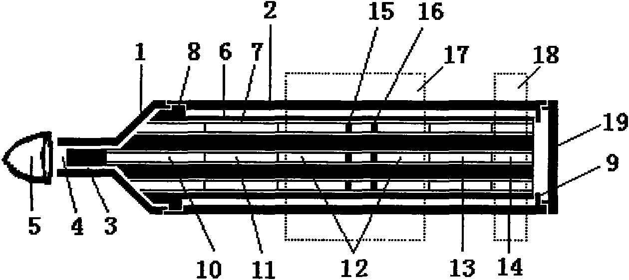
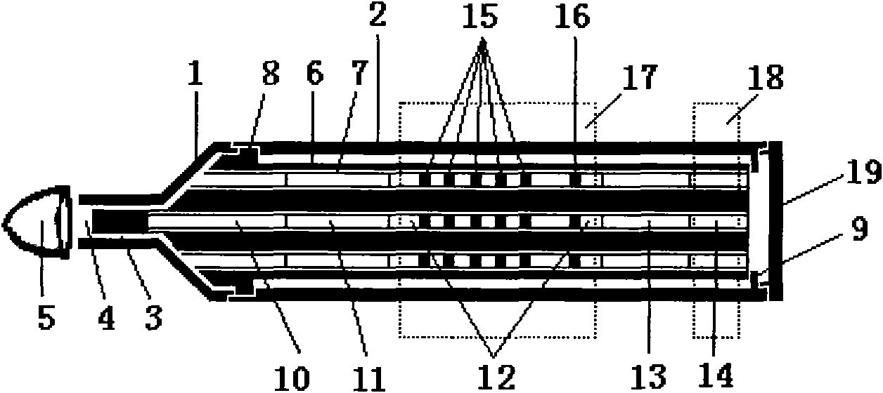
[0036] figure 1 It is a structural view of the preferred scheme 1 of the sample rapid joint detection device of the present invention. The device includes a sample suction head 1 and a detection tube 2 sleeved on the rear end of the sample suction head 1 . The front end of the suction head 1 has a thin tube suction nozzle 3 . The suction nozzle 3 is provided with a sample suction port 4 for sample suction. The front end of the suction nozzle 3 can be covered with a rubber protective cap 5. During the test, the rubber protective cap 5 is removed to expose the sample suction port 4, and the sample joint inspection can be carried out by dipping the suction nozzle 3 in the test product. A test strip attachment column 6 is built in the device, and the surface of the test strip attachment column 6 has one or more longitudinal shallow grooves, a...

Embodiment 2

[0047] Example 2 Operation method of sample rapid joint inspection device

[0048] The joint inspection device (including figure 1 , figure 2 , image 3 , Figure 4 The operation and use method of joint inspection device described in the scheme) is:

[0049] (1) Take out the sample rapid joint inspection device;

[0050] (2) Remove the device head cover 20 of the device and the rubber cap 5 at the front end of the suction head to expose the sample suction port 4, and dip the suction nozzle 3 into the inspection product;

[0051] (3) Within a few minutes, observe the appearance of the built-in test strip strips in the sample color development area of ​​the transparent plastic shell of the detection tube of the device, and judge the negative and positive test results of each index of the test product.


PUM


Abstract

The invention discloses a rapid co-detection device of a sample, which comprises a sample sucking head (1) and a detection pipe (2) which is sleeved at the rear end of the sample sucking head (1). Thefront end of the sample sucking head (1) is provided with a slim-tube suction nozzle (3) on which a rubber protective cap (5) can be sleeved. The device is internally provided with a test bar attached column (6), and the surface of the column body of the test strip attached column (6) is provided with one to more detection test bars (7), wherein shell parts of the detection pipe corresponding toa detection display area (12) and a mounting mark area (14) of each test bar are transparent. The tail end of the detection pipe is provided with a sealing cover (19) which seals waste materials afterdetection into the detection pipe (2). Various indexes of the sample can be simultaneously detected at a time by naked eyes within several minutes by the one-time sample suction and the isomesic detection of the test bars in the device, thus various detections of the sample become simpler, safer and quicker, and cross interferences are also avoided. Meanwhile, the waste materials after the detection are also sealed in the detection pipe so as to be more beneficial to avoiding the spread of pathogens and iatrogenic infections and treating the waste materials in an environment-friendly mode.

Description

technical field [0001] The invention relates to a test strip for joint inspection of medical equipment and samples, in particular to a rapid joint inspection device for samples. Background technique [0002] Colloidal gold immunochromatography (Gold-Immunochromatography Assay, GICA) is an immunolabeling technique developed on the basis of enzyme-linked immunosorbent assay (ELISA). The capillary action of the membrane makes the liquid sample applied on one end of the membrane strip slowly migrate to the other end of the microporous membrane. If there are specific antigens or antibodies in the liquid, they can be combined with immunogold and then fixed on the microporous membrane. Immunogold color is displayed by binding to the corresponding antibody or antigen on the antibody. This technology is simple, fast, and does not require any equipment, and the results can be observed with the naked eye in a few minutes. It is known as "concentrated ELISA" and is now widely used in a...

Claims


Application Information

Patent Timeline
IPC IPC(8): G01N33/52G01N33/558
Inventor 马义才顾敏马灵
Owner 马义才
Why Eureka
Try Eureka