Electronic part mounting apparatus and method of mounting electronic part

一种电子元器件、安装装置的技术,应用在电气元件、电气元件、电固体器件等方向,能够解决接合条件维持管理困难、裕度小等问题,达到接合条件的维持管理容易、确保合格品的效果

Inactive Publication Date: 2010-02-17
PANASONIC CORP
View PDF1 Cites 3 Cited by
  • Summary
  • Abstract
  • Description
  • Claims
  • Application Information

AI Technical Summary

Problems solved by technology

[0018] Or, even if it is possible to find a bonding condition that satisfies the two aspects of ensuring the bonding strength in the entire bonding portion in the electronic component and not destroying the electronic component or the wiring substrate , has also become a joining condition with a small margin required to ensure a good product, and it is very difficult to maintain and manage the joining conditions in mass production

Method used


Image

  • Electronic part mounting apparatus and method of mounting electronic part
  • Electronic part mounting apparatus and method of mounting electronic part
  • Electronic part mounting apparatus and method of mounting electronic part

Examples


Embodiment approach 1

[0048] Figure 1 to Figure 10 Embodiments of the present invention are shown.

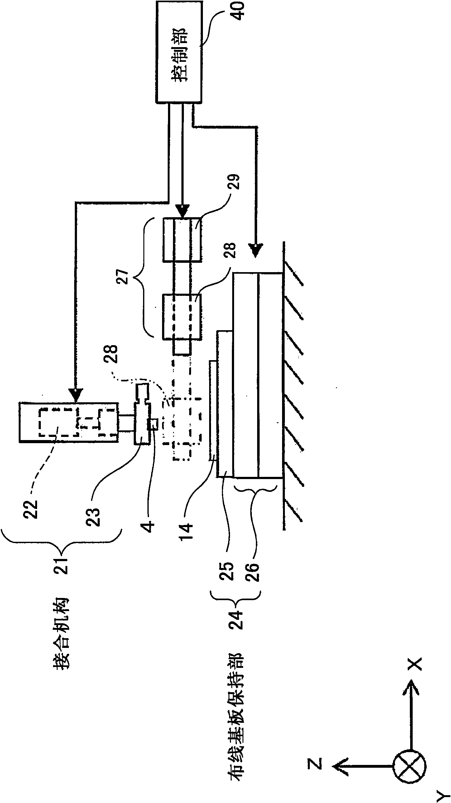
[0049] figure 1 It is a schematic configuration diagram of the ultrasonic bonding device of the present invention.

[0050] This ultrasonic bonding apparatus includes a wiring board holding portion 24 holding a wiring board 14 , and a bonding mechanism 21 for bonding an electronic component 4 to the wiring board 14 is provided on the +Z direction side of the wiring board holding portion 24 . An imaging mechanism 27 for imaging the electronic component 4 and the wiring substrate 14 is provided between the wiring substrate holding portion 24 and the bonding mechanism 21 . Moreover, the supply mechanism (not shown) which supplies the electronic component 4 to the bonding mechanism 21 is provided. In this ultrasonic bonding apparatus, the control unit 40 controls these mechanisms to bond the wiring board 14 and the electronic component 4 .

[0051] The wiring board holding unit 24 includes a table...

Embodiment approach 2

[0097] In addition, in addition to any one of the tools 3 shown in the above-mentioned embodiment 1, it is also possible to Figure 11 or Figure 12The ultrasonic horn 2 is constituted in such a way that the magnitude of the ultrasonic vibration acting on the electronic component 4 is changed.

[0098] Figure 11 It is a partial perspective view showing the ultrasonic horn 2 and the tool 3 according to the second embodiment.

[0099] The hole portion 50 is formed in the ultrasonic horn 2 . In this example, holes 50 are formed on both sides of the tool 3 of the ultrasonic horn 2 in a direction parallel to the ultrasonic vibration direction 5 given by the ultrasonic vibrator 1 . The shape and size of the hole portion 50 are set so that there is no vibration difference between the center portion 3 a and the end portion 3 b of the tool 3 , or the vibration difference is small. In addition, a plurality of hole portions 50 may be formed.

[0100] Figure 12 Among them, the pro...


PUM


Abstract

In the direction parallel to the direction of ultrasonic vibration (5) generated by ultrasonic vibrator (1), the configuration of central part (3a) of tool (3) and the configuration of end part (3b) of the tool (3) are changed from each other so as to be different from each other in cross-sectional area, thereby rendering ultrasonic vibration amplitudes (9) in the direction perpendicular to the direction of ultrasonic vibration (5) substantially identical with each other. Accordingly, the difference between the ultrasonic vibration at the central part (3a) of the tool (3) and that at the end part (3b) of the tool (3) can be zeroed or reduced.

Description

technical field [0001] The present invention relates to an electronic component mounting device and an electronic component mounting method for mounting metal electrodes of electronic components and metal electrodes of wiring boards using ultrasonic vibration. Background technique [0002] In devices for mounting electronic components on wiring substrates such as printed circuit boards, various methods of bonding electrodes of electronic components and electrodes of wiring substrates have been used conventionally as a means of mounting electronic components in a short time and at a relatively low temperature. As one of methods for devices, a bonding method using ultrasonic waves (hereinafter referred to as ultrasonic bonding) is known. [0003] In the above-mentioned ultrasonic bonding, the electronic component pressed on the wiring board is vibrated by ultrasonic vibration, and the electrodes of the electronic component (for example, on which bumps are formed) are electrica...

Claims


Application Information

Patent Timeline
Patent Type & Authority Applications(China)
IPC IPC(8): H01L21/60H01L21/607H05K13/04
CPCH01L2924/14H01L2924/01033H01L2924/01005H01L2924/01006H01L2924/01074H01L2924/01047H01L2924/01004H01L24/81H01L2924/014H01L2224/81801H01L2224/16H01L2224/0554H01L2224/05568H01L2224/05573H01L2924/00014H01L2224/05599H01L2224/0555H01L2224/0556H05K13/04
Inventor 那须博渡边胜彦今村博之蛯原裕小林弘幸
Owner PANASONIC CORP
Why Eureka
Try Eureka