Connector device of cord fabric cutting machine and method thereof

A technology of a joint device and a joint method, applied in the field of joint devices, can solve the problems of aggravating the deflection and scratching of the cloth strip, not completely solving the problems of non-resistance conveying, and inaccurate connection of the head and tail of the cloth strip, so as to achieve the effect of reducing friction.

Active Publication Date: 2010-02-24
MESNAC
View PDF0 Cites 14 Cited by
  • Summary
  • Abstract
  • Description
  • Claims
  • Application Information

AI Technical Summary

Problems solved by technology

Since only half of the cord is powered, and the other half of the cord slides relatively on the stationary conveyor belt, this joint method of centered conveyance does not completely solve the problem of non-resistance conveyance between the two conveyor belts
[0012] In addition, it will further aggravate the d

Method used


Image

  • Connector device of cord fabric cutting machine and method thereof
  • Connector device of cord fabric cutting machine and method thereof
  • Connector device of cord fabric cutting machine and method thereof

Examples


Example Embodiment

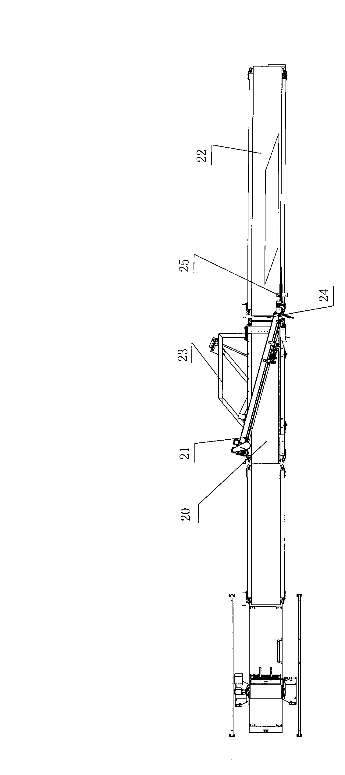
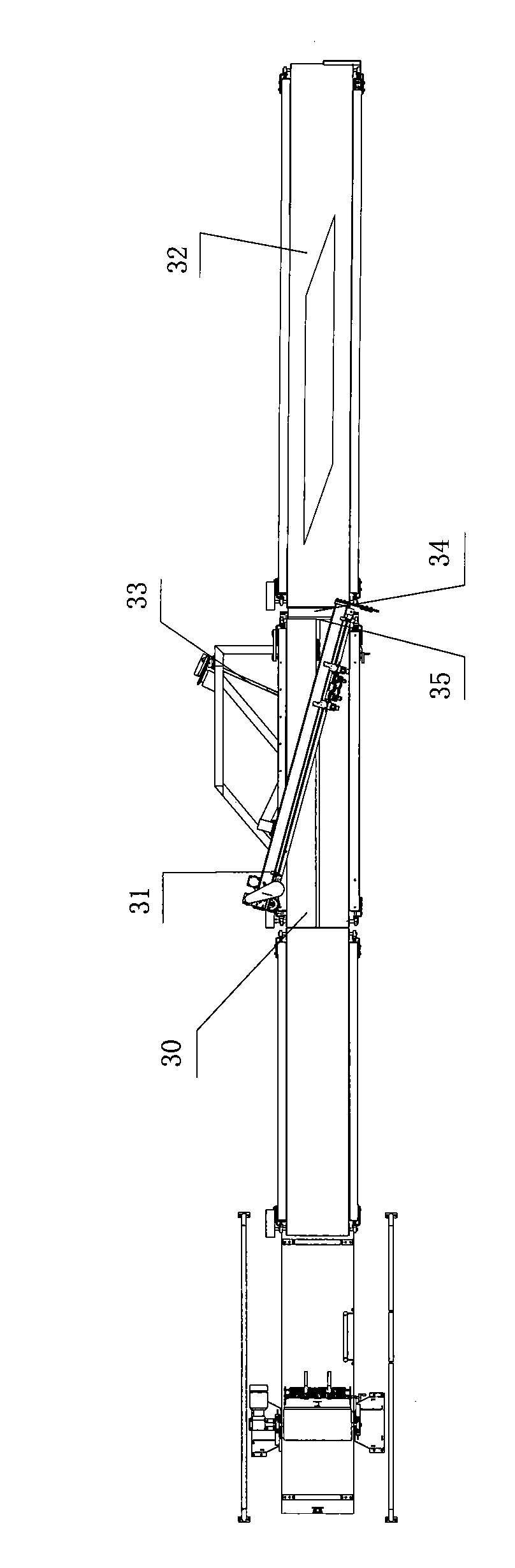
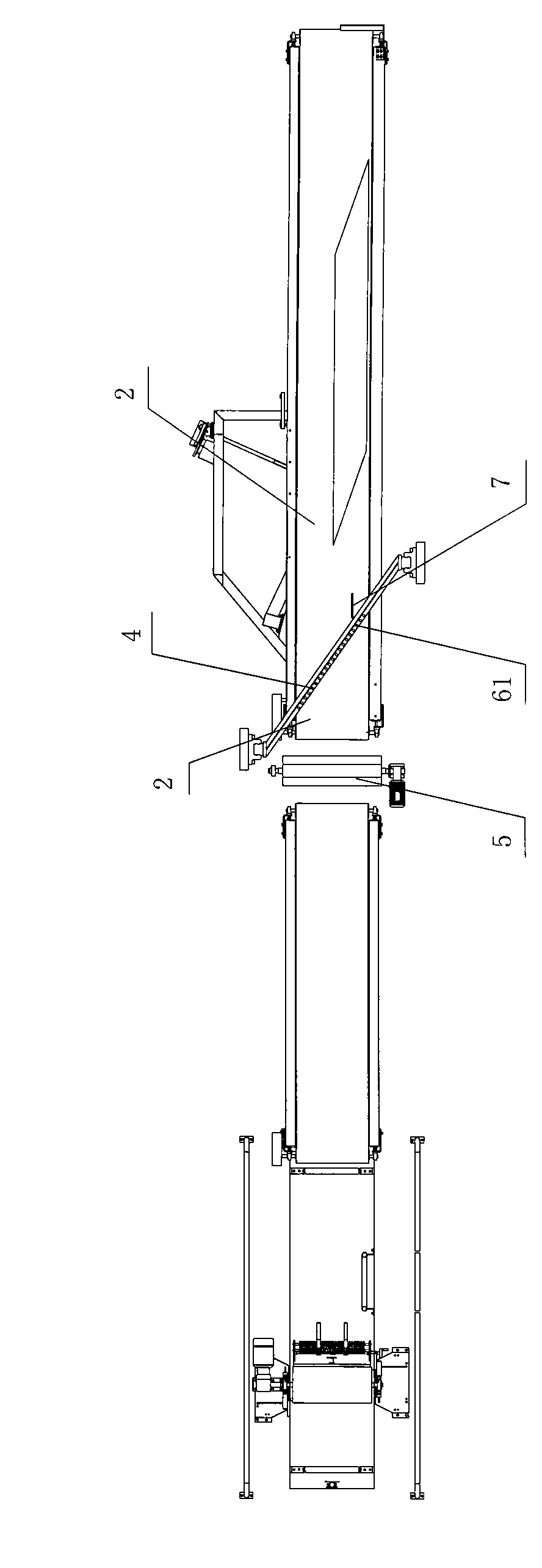
[0058] Example 1, such as Figure 3 to Figure 7-4 As shown, the joint device of the cord cutting machine mainly includes a frame 1 carrying a joint conveyor belt 2, and only one integral joint conveyor belt 2 is provided on the upper part of the frame 1.

[0059] The joint conveyor belt 2 is driven by a servo motor 3 and conveys the curtain along the longitudinal direction of the frame 1, and its longitudinal length is 1.3 times the maximum length of the conveyed curtain.

[0060] The front end of the frame 1 is provided with a joint mechanism 4 for connecting the front and rear curtains together.

[0061] At the front end of the joint conveyor belt 2 is provided a curtain pull-out device 5, the curtain pull-out device 5 includes a vertically fixed pull-out roller 51 and a unidirectional pressure roller 52 arranged above the pull-out roller 51.

[0062] The vertical height of the leading roller 51 is higher than the joint conveyor belt 2.

[0063] On the beam of the joint mechanism 4, ...


PUM


Abstract

The invention provides a connector device of a cord fabric cutting machine and a method thereof, which feed the previous cord fabric and the next cord fabric in sequence forwards by adopting the same integrated connector conveying belt, and lift the tail part of the previous cord fabric from the conveying belt before the connector is stitched and position the cord fabric so as to completely solvethe problem of dynamic shortage of a strip of the cord fabric and realize a resistance-free conveying mode. The connector device of the cord fabric cutting machine is mainly provided with a frame carrying the connector conveying belt, wherein the connector conveying belt is driven by a servo motor and conveys the cord fabric along the vertical direction of the frame; the front end of the frame isprovided with a connector mechanism which is used for connecting the previous cord fabric and the next cord fabric together; the upper part of the frame is only provided with the integrated connectorconveying belt; the vertical length of the conveying belt is larger than the maximum length specification of the conveyed cord fabric; the front end of the connector conveying belt is provided with acord fabric lead device; and a cross beam of the connector mechanism is provided with an adsorption mechanism which is used for upwards lifting and positioning the end part of the cord fabric.

Description

technical field [0001] The invention relates to a joint device applied to a cord cutting machine and a method thereof, belonging to the field of rubber machinery. Background technique [0002] In the existing manufacturing process of various all-steel and semi-steel tires, it is necessary to cut, joint and bond the various rubber components that make up the tire, so as to form the structure of the crown and sidewall of the tire. [0003] At present, the more commonly used cord cutting machine, such as the attached figure 1 As shown, this kind of cord cutting machine adopts the joint method of fixed side conveying. The front end of the joint conveyor belt (20) is equipped with a rotary joint mechanism (21), and the cord strips are transported to the stationary joint conveyor belt (20) through the feeding conveyor belt (22), and a joint conveyor belt (20) is provided on one side The angle adjustment device (23) is provided with a blowing transition plate (24) and a material ...

Claims


Application Information

Patent Timeline
IPC IPC(8): B29D30/38B29D30/46
Inventor 王福业于明进于京云田宝良陈元田韩乐毅
Owner MESNAC
Why Eureka
Try Eureka