Clamping device

A clamping device and clamping technology, applied in textiles and papermaking, continuous winding spinning machines, spinning machines, etc., can solve the problems of insufficient clamping effect, clamping yarn, troublesome removal of winding, etc., to achieve The effect of no residual tube underwinding and reliable clamping effect

Active Publication Date: 2010-02-24
SAURER COMPONENTS GMBH
View PDF2 Cites 4 Cited by
  • Summary
  • Abstract
  • Description
  • Claims
  • Application Information

AI Technical Summary

Problems solved by technology

[0003] This clamping device has the following disadvantages, on the one hand, it is very troublesome to remove the winding, this is because the winding yarn is not thrown out when opening the clamping gap, and on the other hand, when the winding spindle axis is less than 360° The clamping effect of the surface pressure is not sufficient to reliably clamp the yarn during operation

Method used


Image

  • Clamping device
  • Clamping device
  • Clamping device

Examples


Embodiment Construction

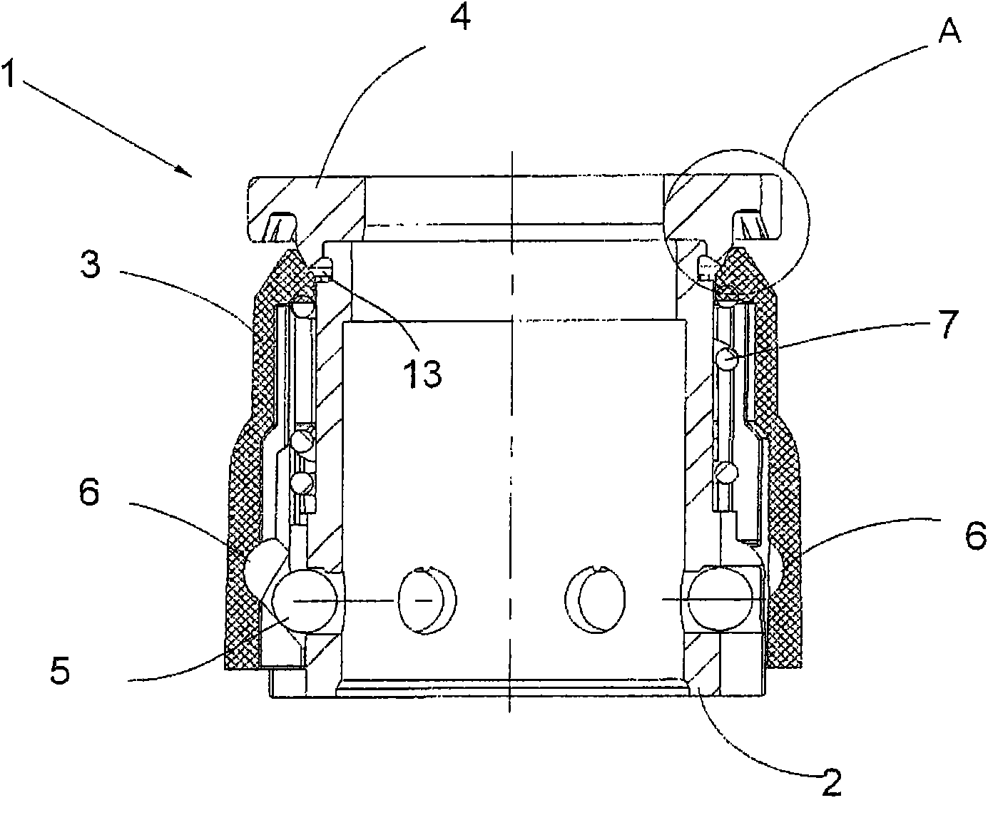
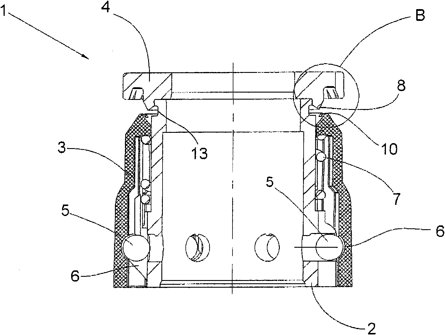
[0030] figure 1 A clamping device 1 is shown, which can be attached to the upper part of a spindle for a spinning or twisting machine or to the drive spindle of the spindle. The clamping device 1 according to the invention is used, for example, for clamping yarns during winding of finished bobbins. figure 1 The clamping device 1 shown is actuated by centrifugal force and can assume two positions - a clamped position and an open position, wherein, as figure 1 Shown in the clamping position the yarn is clamped between two clamping elements, while in the open position (eg image 3 shown) can feed the yarn or can release and throw out the previously clamped yarn.

[0031] The clamping device 1 comprises a tube bottom winding sleeve 2 which is arranged on a spindle or on a spindle (the spindle is arranged on the spindle). Furthermore, the clamping device 1 has a sliding sleeve 3 which is displaceable relative to the underwinding sleeve 2 in the longitudinal direction of the spin...


PUM


Abstract

The invention relates to a clamping device 1 on spindle of a spinning machine and a twisting machine for yarning, wherein, a basically cylindrical clamping device 1is provided on the upper par to the spindle, the clamping device 1 includes a fixed clamping element 4 and a clamping element 3 that can be pressed on the fixed clamping element 4 and can move in the axial direciton, an orientation force can be applied to the the clamping element 3, the orientation force makes the movable clamping element 3 to maintain a space from the fixed clamping element 4 in the axial direciton, namely, a clamp clearance is formed between these clamp elements,the yarn to be clamped can be introduced into the clamp clearance, wherein, the clamping device 1 has a ring projecting part 8 pointing to the clamp clearance 12 on one of these clamp elements 3,4, the ring projecting part 8 is supported on contact faces 9,11 with uninterrupted surface of the other clamp element to clamp the yarn.

Description

technical field [0001] The invention relates to a clamping device for yarn on the spindles of spinning and twisting machines, wherein a substantially cylindrical clamping device is arranged on the spindle upper part of the spindle, said clamping device comprising a fixed clamping clamping element and an axially movable clamping element which can be pressed against said fixed clamping element by spring force, said axially movable clamping element can be applied with a force directed against the spring force, so The force keeps the movable clamping elements axially at a distance from the fixed clamping elements, ie a clamping gap is formed between these clamping elements into which the yarn to be clamped can be introduced. Background technique [0002] DE 42 25 964 A1 already discloses a clamping device of the type mentioned in the introduction, which is arranged on the spindle shaft. The spindle shaft is inserted on the spindle disc, on which a sliding sleeve is pushed and i...

Claims


Application Information

Patent Timeline
Patent Type & Authority Applications(China)
IPC IPC(8): D01H7/04
CPCD01H1/38
Inventor 克劳斯·梅特戈特弗里德·施陶登迈尔
Owner SAURER COMPONENTS GMBH
Why Eureka
Try Eureka