Roller shutter and roller shutter system manufactured by applying same

A technology of roller blinds and reels, applied in the field of roller blind systems, which can solve problems such as easy tilting and unstable operation of roller blinds

Active Publication Date: 2014-08-20
HD4U SMART HOME CO LTD
View PDF7 Cites 3 Cited by
  • Summary
  • Abstract
  • Description
  • Claims
  • Application Information

AI Technical Summary

Problems solved by technology

[0005] At the same time, the present invention also provides a roller blind that can effectively prevent the reel assembly from tilting, and the roller blind runs stably and is not easy to fall o

Method used


Image

  • Roller shutter and roller shutter system manufactured by applying same
  • Roller shutter and roller shutter system manufactured by applying same
  • Roller shutter and roller shutter system manufactured by applying same

Examples


Embodiment 1

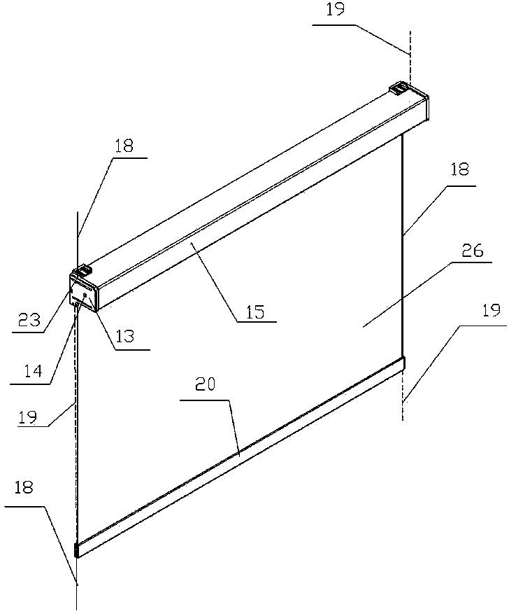
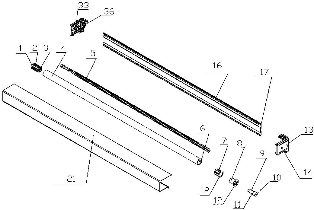
[0041] Such as figure 1 As shown, a roller blind includes a reel assembly 15 located at the upper end of the curtain 26 and a floor assembly 20 located at the lower end of the curtain 26 . The reel assembly 15 includes a reel 4 and end caps 13 located at both ends of the reel 4 , and a curtain 26 is wound around the reel 4 . A sleeve cover 21 and a reel rear cover 16 are connected between the two end covers 13. The reel cover 21 and the reel rear cover 16 form a cavity, and the reel 4 is installed in the cavity.

[0042] There are two ropes arranged at the two ends of the curtain, and the two ends of the two ropes are respectively fixed on the fixtures outside the roller blind, such as on the window frame or the wall (not shown), and the reel assembly 15 passes through the inlet on the end cover. The wire hole connects the reel assembly to the rope, and the reel assembly can move up and down on the rope. The base plate assembly passes through the wire channel 29 on the base c...

Embodiment 2

[0052] Such as Figure 8 As shown, the difference from Embodiment 1 is that the bottom plate assembly 20 is on the top, and the reel assembly 15 is on the bottom. The second wire inlet hole 22 at the lower end of the end cover 13 passes through, and the second wire inlet hole 22 is located at the rear end of the first wire inlet hole 24, which can effectively prevent the reel assembly 15 from being tilted and unstable.

Embodiment 3

[0054] Such as Figure 9 As shown, the difference from Embodiment 1 is that the rope is fixed on the reel assembly, and the reel assembly is fixed on a fixed object such as a roller blind, such as a wall or a window frame. The fixing of the reel assembly is through the end cover 13 and the end cover. The connection between the end cover cover plate 43 on the outside of 13 is realized.

[0055] There is an end cover cover 43 on the outside of the end cover 13, and the end cover cover 43 is "L" shaped. On one side of the end cover cover 43, there are two fixing holes 48 for the end cover cover. Plate 43 is fixed on the body of wall or form, just on the fixture other than roller blind, and the other limit of end cover cover plate is integrally formed with positioning protrusion 44, and the length of positioning protrusion 44 is the same as end cover 13 outer sides. The length of the positioning grooves 42 on the top is the same, because there are three positioning grooves 42 arr...


PUM


Abstract

The invention relates to a roller shutter structure, in particular to a roller shutter and a roller shutter system manufactured by applying the roller shutter. The roller shutter comprises roller shutter cloth, one end of the roller shutter cloth is wound around a reel assembly, the other end of the roller shutter cloth is fixed to a bottom plate assembly, the two sides of the roller shutter are respectively provided with a guide part, the guide parts are connected to the reel assembly and the bottom plate assembly in a wound mode respectively, and at least one of the reel assembly and the bottom plate assembly which are located at the two ends of the roller shutter cloth can move up and down along the guide parts. The roller shutter system is of the structure formed by connecting more than two roller shutters through one guide part. The roller shutter system is simple in structure and convenient to operate, the shielding position can be selected freely, the fixing positions of the two ends of the roller shutter cloth of the roller shutter can be adjusted directly, and the roller shutter system is manufactured by applying the roller shutter; the technical problems that in the prior art, shielding has to be performed from top to bottom according to the shielding position of the roller shutter cloth, the winding mode of the roller shutter cloth is single, and a winding structure is complex are solved.

Description

technical field [0001] The invention relates to a rolling blind structure, in particular to a rolling blind with adjustable components at both ends of the curtain and a rolling blind system made by using the rolling blind. Background technique [0002] As an important part of indoor lighting and lighting, windows are indispensable in current house construction. Curtains or roller blinds are generally installed on the windows for use as shading or windshield. The roller blind generally includes a reel assembly and a bottom plate assembly located at both ends of the curtain. The reel assembly includes a reel for winding the curtain, a curtain and an end cover, and the bottom plate assembly is fixed on the other end of the curtain. The current roller blinds generally use the pull rope on one side of the roller blind to drive the roller of the roller blind to rotate, thereby driving the curtain fixed on it to move, or to automatically drive the curtain of the roller blind to be...

Claims


Application Information

Patent Timeline
IPC IPC(8): E06B9/42E06B9/56
Inventor 斯特凡·谢林
Owner HD4U SMART HOME CO LTD
Why Eureka
Try Eureka