Wire winding core and wire unwinding mechanism

A winding and stretching technology, which is applied in the field of iron core winding, can solve problems such as low efficiency and unstable rhythm of manual wire management, and achieve the effects of improving efficiency, saving labor costs, and stabilizing the rhythm of wire management

Active Publication Date: 2020-09-01
SZ DJI TECH CO LTD
View PDF12 Cites 4 Cited by
  • Summary
  • Abstract
  • Description
  • Claims
  • Application Information

AI Technical Summary

Problems solved by technology

[0003] Generally, there are a large number of lead wires from motor coils, and manual work can only be done one by one, which is inefficient. In addition, the rhythm of manual wire management in traditional methods is unstable, which further leads to low efficiency and is difficult to integrate with other automated processes.

Method used


Image

  • Wire winding core and wire unwinding mechanism
  • Wire winding core and wire unwinding mechanism
  • Wire winding core and wire unwinding mechanism

Examples


Embodiment Construction

[0053] In order to understand the above-mentioned purpose, features and advantages of the present invention more clearly, the present invention will be further described in detail below in conjunction with the accompanying drawings and specific embodiments. It should be noted that, in the case of no conflict, the embodiments of the present application and the features in the embodiments can be combined with each other.

[0054] In the following description, many specific details are set forth in order to fully understand the present invention. However, the present invention can also be implemented in other ways than described here. Therefore, the protection scope of the present invention is not limited by the specific implementation disclosed below. Example limitations.

[0055] The following describes the winding core and the winding mechanism according to some embodiments of the present invention with reference to the accompanying drawings.

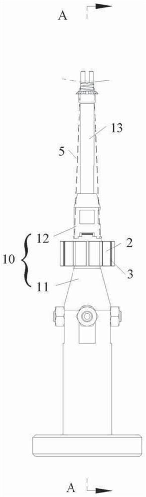
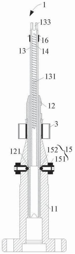
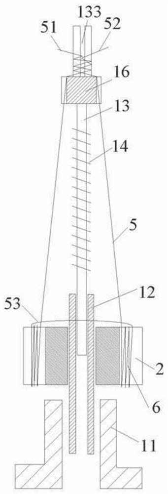
[0056] Such as Figure 1 to Fi...


PUM


Abstract

A wire winding core (1) and a wire unwinding mechanism (4) are disclosed. The wire winding core (1) comprises a base assembly (10), a first drive device, and a telescopic rod (13). The base assembly (10) is used for mounting an iron core (2). The first drive device is connected to the base assembly (10) to drive the base assembly (10) to rotate. The telescopic rod (13) is connected to the base assembly (10), and can extend/retract with respect to the base assembly (10) along an extension direction of the telescopic rod (13). When the first drive device drives the base assembly (10) to rotate,the iron core (2) rotates along with the base assembly (10) to wind a lead-out wire (5) on the iron core. Because the telescopic rod (13) can extend/retract with respect to the base assembly (10), thelead-out wire (5) can be in a straight suspension state after passing through the telescopic rod (13), thereby providing a foundation for subsequent automatic assembling of a PCB board (9), automaticsoldering of the lead-out wire (5), and automatic breaking of a tail.

Description

technical field [0001] Embodiments of the present invention relate to the technical field of iron core winding, and more specifically, relate to a winding core and a winding mechanism. Background technique [0002] In order to achieve a compact structure, the motor core often does not design the pin or similar structure of the lead wire, but the circuit function PCB is assembled in the later stage, and the lead wire is soldered to the PCB to realize the circuit lead. The main process is: winding, assembling PCB, welding, splitting tail wire. In the traditional method, in the coil winding process, the lead-out wire lacks effective retention and is in a free and amorphous state. In the PCB board assembly process, it is necessary to manually straighten the lead wires before assembling the PCB board. [0003] Generally, there are a large number of lead-out wires from motor coils, and manual work can only be done one by one, which is inefficient. In addition, the rhythm of manu...

Claims


Application Information

Patent Timeline
Patent Type & Authority Applications(China)
IPC IPC(8): H02K15/08
CPCH02K15/08H02K15/00
Inventor 梁敬天吴阳阳吴韬
Owner SZ DJI TECH CO LTD
Why Eureka
Try Eureka