A low-voltage wire-wound pneumatic brake tension device

A pneumatic braking and tensioning device technology, applied in the manufacture of inductors/transformers/magnets, electrical components, circuits, etc., can solve the problems of high labor intensity, poor working environment, low automation of low-voltage winding, etc., to improve product quality The effect of quality, reduced intervention, and increased product production efficiency

Pending Publication Date: 2019-01-15
昆明供电设计院有限责任公司
View PDF0 Cites 4 Cited by
  • Summary
  • Abstract
  • Description
  • Claims
  • Application Information

AI Technical Summary

Problems solved by technology

[0005] Aiming at the deficiencies of the prior art, the present invention provides a low-voltage winding pneumatic brake tensioning device, which solves the problems of low automation of low-voltage winding, low production efficiency, high labor intensity and poor working environment

Method used


Image

  • A low-voltage wire-wound pneumatic brake tension device
  • A low-voltage wire-wound pneumatic brake tension device
  • A low-voltage wire-wound pneumatic brake tension device

Examples


Embodiment 1

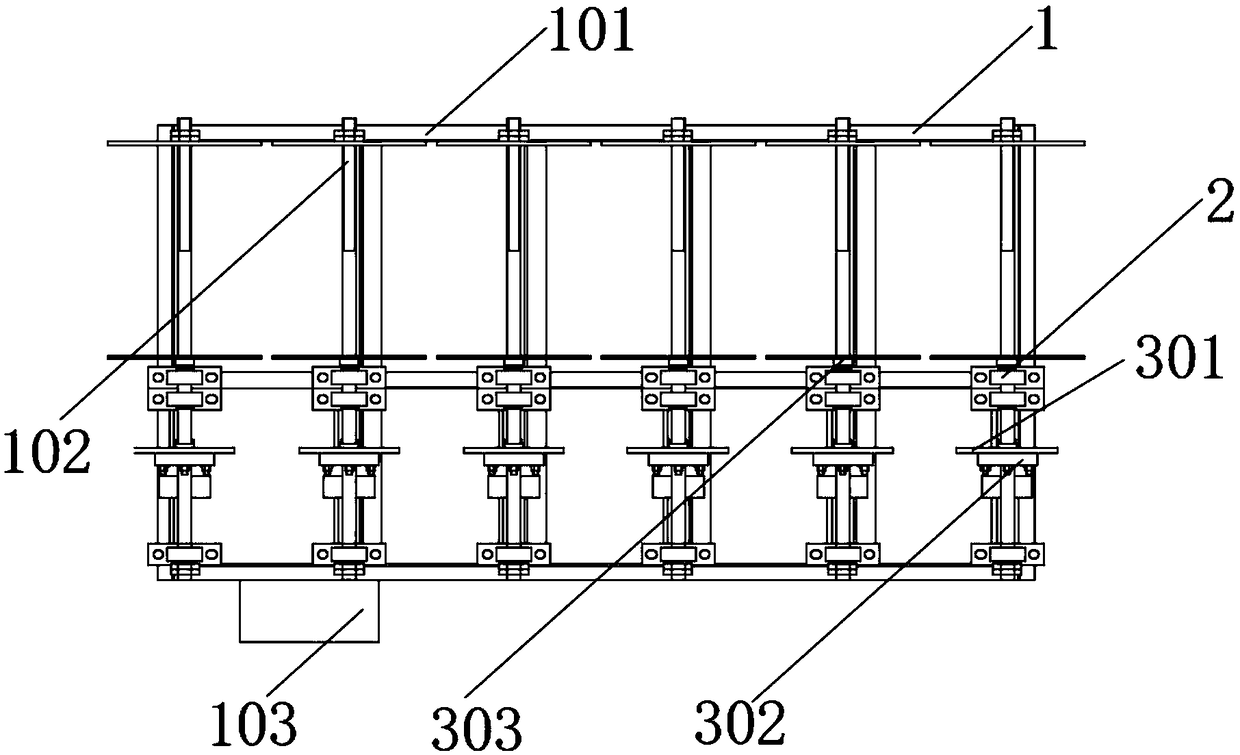
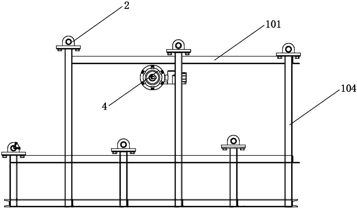
[0032] Such as Figure 1-8 As shown, the embodiment of the present invention provides a low-voltage winding pneumatic brake tensioning device, including a main support frame assembly 1, a main reel assembly 3 is vertically provided on the top of the main support frame assembly 1, and the main reel assembly The end of 3 is sleeved with a support shaft seat assembly 2, and one side of the main reel assembly 3 is provided with a brake assembly 4. The main support frame assembly 1 includes a horizontal horizontal truss 101, and the horizontal horizontal truss 101 is bolted to the vertical position on the same horizontal plane. There is a horizontal longitudinal truss 102, and the angle between the horizontal transverse truss 101 and the horizontal longitudinal truss 102 is vertically bolted to a vertical support truss 104, and the middle part of the vertical support truss 104 is bolted to a main electric control box 103, and the main electric control box 103 Including the main ele...

Embodiment 2

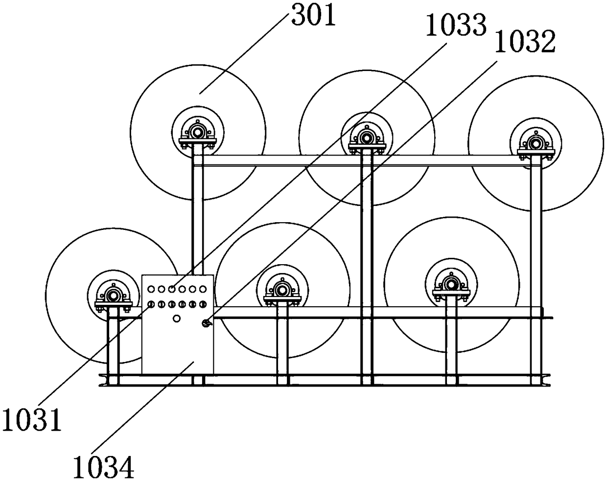
[0034] Such as figure 1 , 2 , 5, 7, and 8, the embodiment of the present invention provides a low-voltage winding pneumatic brake tensioning device, the support shaft seat assembly 2 includes a bearing base 203, and the top outer surface of the bearing base 203 is vertically provided with a bearing stop Frame 201, the middle part of the bearing limit frame 201 is fitted with a support bearing 202, and the transition fit between the support bearing 202 and the bearing limit frame 201, the surface side of the bearing base 203 is fitted with a tightening limit bolt 205, the bearing The bottom of the base 203 is fitted with a rubber spacer 204, and the maximum shrinkage thickness of the rubber spacer 204 is 0.5 mm. The main reel assembly 3 includes a brake dial 301, and the surface of the brake dial 301 is bolted with The brake flywheel 302, and the installation positions between the brake dial 301 and the brake flywheel 302 are coaxial with each other. On the coaxial line, the ...

Embodiment 3

[0036] Such as image 3 , 6 As shown, the embodiment of the present invention provides a low-voltage winding pneumatic brake tensioning device. The brake assembly 4 includes a main air pressure drum 401. The end of the main air pressure drum 401 is vertically bolted with a return spring 402, and one end of the return spring 402 is vertically Pinned with main brake arm 403, the parallel position of main brake arm 403 is pin-connected with auxiliary brake arm 408 at the other end of back-moving spring 402, and the middle part of main brake arm 403 and auxiliary brake arm 408 is provided with brake pin splint 407 in parallel, brake The middle part of the pin splint 407 is fitted with a brake arm pin shaft 404, the ends of the main brake arm 403 and the auxiliary brake arm 408 are provided with a brake pawl 405, and the junction of the brake pawl 405 and the main brake arm 403 is fitted with a brake pin shaft 406.


PUM


Abstract

A low-voltage wire-wound pneumatic brake tension device is provided. The invention relates to the technical field of transformer winding automation equipment. The low-voltage winding pneumatic brake tension device comprises a main support frame assembly, a main winding wheel assembly is vertically arranged on the top of the main support frame assembly, an end of the main winding wheel assembly issleeved with a support shaft base assembly, and a brake assembly is arranged on one side of the main winding wheel assembly. The flywheel of the whole equipment is clamped by a pneumatic butterfly brake, so as to realize the clamping of the whole equipment, thereby realizing the tension of the conductor, and realizing 1- 12 groups of different copper wires are used for winding operation so as to realize the winding operation of copper wires with different number of wire groups, and the whole equipment is controlled by adopting electric equipment, so as to reduce manual intervention, improve product quality and increase product production efficiency.

Description

technical field [0001] The invention relates to the technical field of transformer winding automation equipment, in particular to a low-voltage winding pneumatic brake tensioning device. Background technique [0002] Transformer low-voltage coil wires are generally oxygen-free pure copper flat wires. The size of each wire is similar to that of two chopsticks, with high hardness and toughness. When the coil is wound, the wire has a tension force to tighten the wire to ensure the coil winding size, improve the winding size requirements, make the winding tight, and improve the coil quality. At the same time, employees can wind without a lot of labor Pulling the wire strongly can reduce the injury to the employee's wrist, which has a great advantage in improving the occupational health and safety of the employee. [0003] The present invention mainly solves the problem that the existing low-voltage winding method can only be manually operated, so as to increase production effic...

Claims


Application Information

Patent Timeline
IPC IPC(8): H01F41/094H01F41/061
CPCH01F41/061H01F41/094
Inventor 李彬
Owner 昆明供电设计院有限责任公司
Why Eureka
Try Eureka