Fixed stroke synchronizer

A technology of synchronizer and stroke, applied in the direction of sliding valve, transmission parts, engine components, etc., can solve the problems of insufficient shifting quality, high noise, and easy release of steel balls.

Active Publication Date: 2010-02-24
SHANGHAI AUTOMOBILE GEAR WORKS
View PDF1 Cites 9 Cited by
  • Summary
  • Abstract
  • Description
  • Claims
  • Application Information

AI Technical Summary

Problems solved by technology

[0003] After searching the existing technology, it is found that the Chinese invention patent application number 94112951.9 and the publication number CN 1123746A record a "gearbox synchronizer". This technology mainly improves the design of the speed-regulating copper ring in the traditional synchronizer to increase the copper The strength of the ring and the capacity of the synchronizer, and use a coil spring instead of a linear spring to solve the problem of uneven force on the speed control key
However, the synchronizer slider and the synchronizer gear sleeve in this prior art are in surface contact, and there are defects in the transmission shift force not being stable enough, the shift quality not high enough and the noise being too large during the synchronization process. In addition, the spring, slider , Steel ball assembly is difficult, and the steel ball is easy to come out when shifting gears

Method used


Image

  • Fixed stroke synchronizer
  • Fixed stroke synchronizer
  • Fixed stroke synchronizer

Examples


Embodiment Construction

[0022] The embodiments of the present invention are described in detail below. This embodiment is implemented on the premise of the technical solution of the present invention, and detailed implementation methods and specific operating procedures are provided, but the protection scope of the present invention is not limited to the following implementation example.

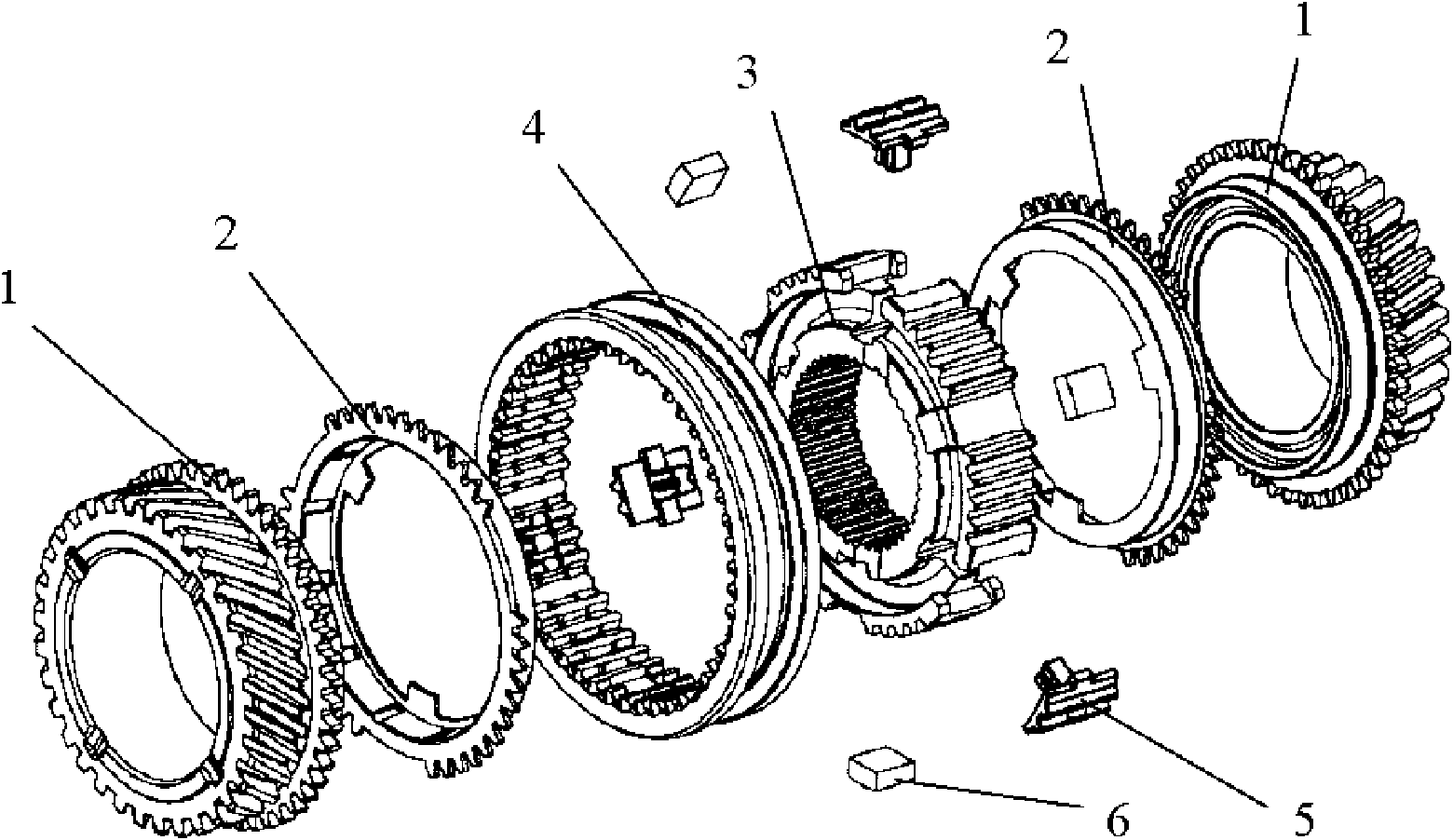
[0023] Such as figure 1 As shown, this embodiment includes: combined teeth 1, synchronous ring 2, gear hub 3, gear sleeve 4, integrated slider 5 and positioning device 6, wherein: the integrated slider 5 is arranged on the outer edge of the gear hub 3, and the integrated slider The block 5 is clamped with the gear sleeve 4, the positioning device 6 is set on the inner edge of the gear sleeve 4, the gear hub 3 is socketed with the gear sleeve 4, and two sets of synchronous rings 2 and coupling teeth 1 with the same structure are sequentially arranged from inside to outside. The mirror is symmetrically sleeved on bo...


PUM


Abstract

The invention relates to a fixed stroke synchronizer in the technical field of automotive engineering, comprising conjunction gears, synchronizer rings, a gear hub, a gear sleeve, an integrated moduleand a positioning device. The integrated module is arranged on the outer edge of the gear hub and clamped on the gear sleeve; the positioning device is arranged on the inner edge of the gear sleeve which is sleeved on the gear hub; and the two synchronizer rings and the two conjunction gears in the same structures are sequentially sleeved at both sides of the gear sleeve from interior to exteriorin a mirrorsymmetry mode. The synchronizer with the anti-extrusion integrated module simplifies the structure, eliminates shifting failures, even synchronizer failures due to the extrusion of a steelball of the integrated module out of the gear sleeve while shifting and effectively lowers noise generated during shifting.

Description

technical field [0001] The invention relates to a device in the technical field of automobile engineering, in particular to a fixed stroke synchronizer. Background technique [0002] A car synchronizer is a mechanical device that enables a car to shift gears smoothly. In the manual mechanical transmission (MT), in order to realize the quick, light and shock-free shifting operation, and improve the power and fuel economy of the car, synchronizers are often used to realize the shifting operation. The structure types of synchronizers generally include atmospheric pressure synchronizers, inertial synchronizers, and inertial booster synchronizers. Among them, the inertia synchronizer is widely used in China because it can ensure synchronous meshing shift and has a simple structure. According to the structure, the inertia synchronizer can be divided into lock ring type inertia synchronizer, lock pin type inertia synchronizer, lock ring type multi-cone inertia synchronizer and so...

Claims


Application Information

Patent Timeline
Patent Type & Authority Applications(China)
IPC IPC(8): F16K3/12F16H57/00
Inventor 孔文凯张文鑫
Owner SHANGHAI AUTOMOBILE GEAR WORKS
Why Eureka
Try Eureka