High-temperature resistant corrugated expansion joint

A corrugated expansion joint and high temperature resistance technology, applied in the field of pipeline expansion joints, can solve the problems of pipeline matching that are not suitable for high temperature medium, and achieve the effects of improving the heat insulation effect, easy production and simple overall structure

Inactive Publication Date: 2010-02-24
JIANGSU XINFANGYUAN ELECTRIC EQUIP MFG
View PDF0 Cites 2 Cited by
  • Summary
  • Abstract
  • Description
  • Claims
  • Application Information

AI Technical Summary

Problems solved by technology

The products in the prior art are not suitable for supporting pipelines conveying high-temperature media because they can only be used at room temperature

Method used


Image

  • High-temperature resistant corrugated expansion joint
  • High-temperature resistant corrugated expansion joint

Examples


Embodiment Construction

[0014] The present invention will be further described below according to accompanying drawing.

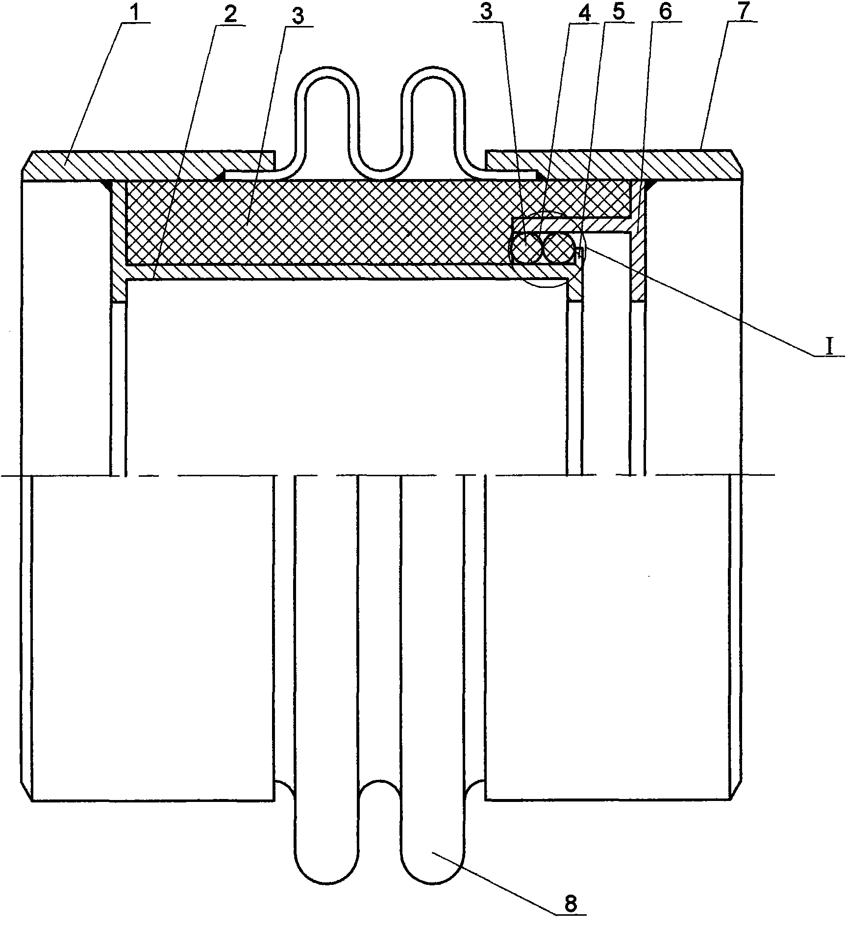
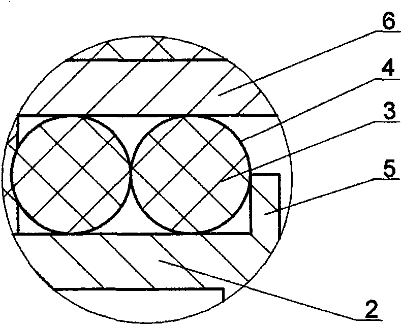
[0015] figure 1 The shown high temperature corrugated expansion joint is used on the steelmaking furnace exhaust duct, and it includes a cylindrical left connecting pipe 1, a bellows 8 and a right connecting pipe 7 which are sequentially sealed and connected. The inner wall of the left connecting pipe 1 is fixedly connected to the guide tube 2 opening to the right, and the inner wall of the right connecting tube 7 is fixedly connected to the auxiliary guide tube 6 opening to the left. The inner diameter of the shorter auxiliary guide tube 6 is greater than the outer diameter of the guide tube 2 , both coaxial and partially fitted. At the gap between the guide tube 2 and the auxiliary guide tube 6, there is a sealing structure that can move relative to the axial direction, which is formed by the metal mesh 4 cover heat insulation material 3. The annular boss 5 seals, not only pre...


PUM


Abstract

The invention discloses a high-temperature resistant corrugated expansion joint which comprises a left connecting pipe, a corrugated pipe and a right connecting pipe which are sequentially connected in a seal way, wherein the inner wall of the left connecting pipe is fixedly connected with a flow guide cylinder opened to the right, and the inner wall of the right connecting pipe is fixedly connected with an accessory flow guide cylinder opened to the left; the inner diameter of the accessory flow guide cylinder with less length is larger than the outer diameter of the flow guide cylinder, andthe accessory flow guide cylinder and the flow guide cylinder are coaxial and are partially sleeved. A heat insulation material sleeved by a metal mesh is arranged in a clearance between the outer wall surfaces of the flow guide cylinder and the accessory flow guide cylinder and the inner walls of the left connecting pipe, the corrugated pipe and the right connecting pipe to form a heat insulationstructure. A heat insulation material sleeved by a metal mesh is also arranged between sleeving sections of the flow guide cylinder and the accessory flow guide cylinder to form a seal structure which can relatively move axially. The heat insulation structure is arranged in the high-temperature resistant corrugated expansion joint, and the corrugated pipe still maintains enough structural strength without the influence of medium temperature, normally plays a role of absorption or compensation and ensures the safe running of the configured pipeline.

Description

technical field [0001] The invention relates to a pipeline accessory, in particular to a pipeline expansion joint. Background technique [0002] Steelmaking furnace is a kind of high-temperature melting equipment. Its hot air and flue gas exhaust pipes work in a harsh environment, and the pipes will expand or shrink correspondingly with the change of the temperature of the conveying medium. The expansion or shrinkage of the pipeline directly produces axial displacement and axial force. These physical changes are one of the factors that constitute instability and unsafety of the pipeline network. In engineering, expansion joints are usually installed at the joints of the pipelines, and the flexible deformation characteristics of the bellows are used to absorb or compensate the axial displacement and axial force of the pipelines, so as to directly improve the operation conditions of the pipelines. Under the condition of normal temperature, the products of the prior art are fu...

Claims


Application Information

Patent Timeline
Patent Type & Authority Applications(China)
IPC IPC(8): F16L51/02F16L27/12D01F9/08
Inventor 杨朋中
Owner JIANGSU XINFANGYUAN ELECTRIC EQUIP MFG
Why Eureka
Try Eureka