Cast-in-place pile integrity optical fiber ultrasonic detection device and detection method thereof

A detection device, ultrasonic technology, applied in the direction of using sound wave/ultrasonic wave/infrasonic wave to analyze solids, analyze materials, instruments, etc. It can solve the problems of inaccurate measured waveform, inability to judge defects, and inaccurate positioning, so as to reduce the difficulty of measurement, Reduce testing costs and overcome survival effects

Pending Publication Date: 2022-05-06
NANJING UNIV
View PDF1 Cites 0 Cited by
  • Summary
  • Abstract
  • Description
  • Claims
  • Application Information

AI Technical Summary

Problems solved by technology

The exciter is fixed at the center of the pile head, and the strain-sensing optical fiber embedded in the main steel bar can receive the stress wave within the entire pile body, thereby realizing the integrity detection of the entire bored pile. position and the position of the pile bottom produce multiple reflections and transmissions, and the measured waveform is very inaccurate. Within a certain range below the pile top, the uplink reflection signal overlaps with the high-energy incident wave, and it is impossible to judge the defects in this range; The wave propagates downward and attenuates, and it is destined that this method can only detect shorter piles;
[0009] 4. This patent uses a distributed acoustic wave sensor demodulator to collect optical fiber strain data in the pile body, and then converts the so-called measured strain data into acoustic wave data. Multiple conversions cause signal attenuation, thereby making positioning inaccurate

Method used


Image

  • Cast-in-place pile integrity optical fiber ultrasonic detection device and detection method thereof
  • Cast-in-place pile integrity optical fiber ultrasonic detection device and detection method thereof
  • Cast-in-place pile integrity optical fiber ultrasonic detection device and detection method thereof

Examples


Embodiment Construction

[0036] The conception, specific structure and technical effects of the present invention are clearly and completely described below in conjunction with the embodiments and accompanying drawings, so as to fully understand the purpose, scheme and effect of the present invention. It should be noted that the embodiments in the present application and the features in the embodiments can be combined without conflict. It should be noted that, unless otherwise specified, when a feature is called "fixed" or "connected" to another feature, it can be directly fixed and connected to another feature, or indirectly fixed and connected to another feature. on a feature. In addition, descriptions such as up, down, left, and right used in the present invention are only relative to the mutual positional relationship of the components of the present invention in the drawings.

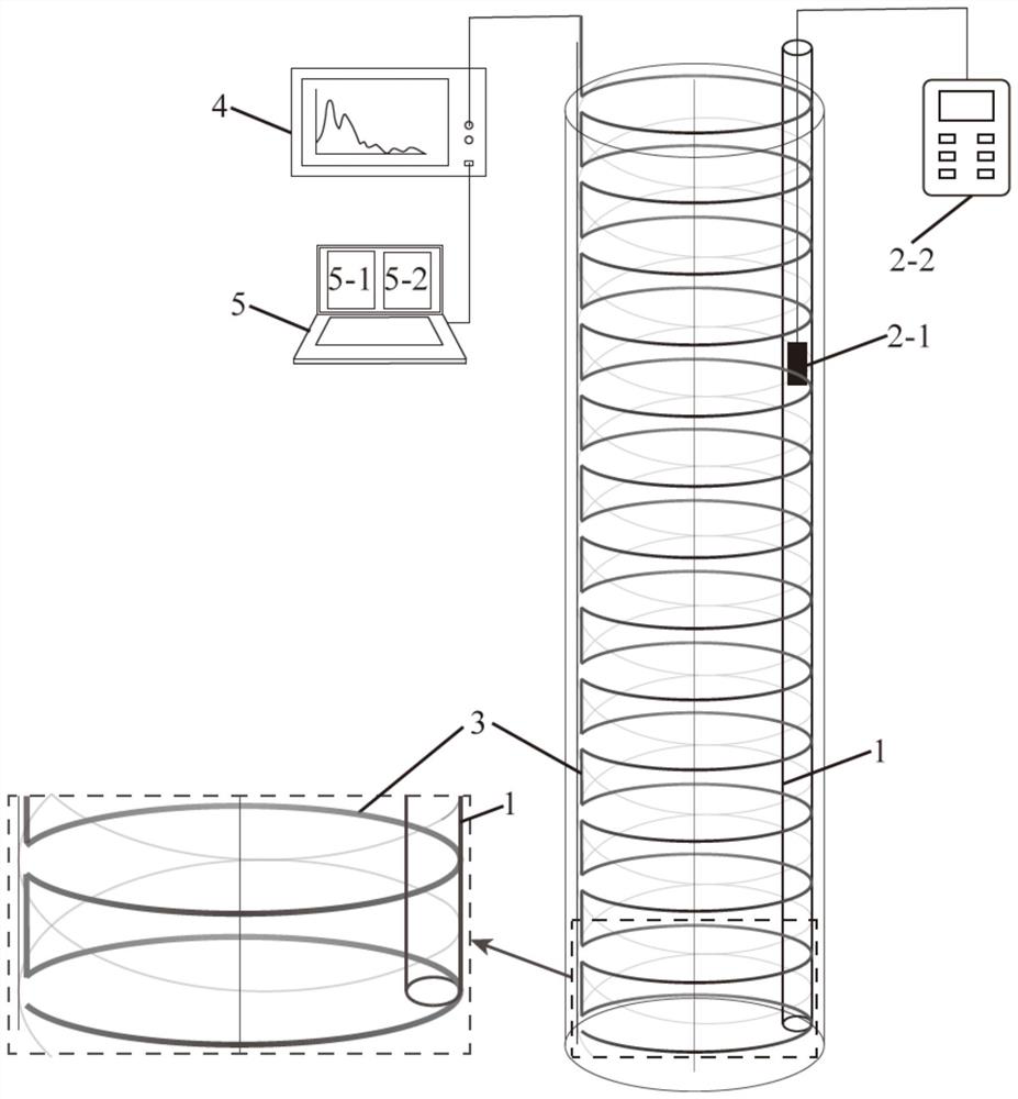
[0037] like figure 1 As shown, acoustic measuring tube 1, ultrasonic transmitting transducer 2-1, controller 2-2, sens...


PUM


Abstract

The invention relates to the technical field of cast-in-place concrete pile body defect detection, in particular to a cast-in-place pile integrity optical fiber ultrasonic detection device and a detection method thereof. An ultrasonic transmitting unit comprises at least one sounding pipe, an ultrasonic transmitting transducer and a controller; the data acquisition unit comprises a sensing optical cable and a distributed sound wave sensing demodulator; the data analysis unit comprises a cast-in-place pile integrity evaluation module; the sensing optical cable is wound on a reinforcement cage, the sounding pipe is fixed to one side of the reinforcement cage, the ultrasonic transmitting transducer is arranged in the sounding pipe in a liftable mode and electrically connected to the controller, and the sensing optical cable is electrically connected to the cast-in-place pile integrity evaluation module through the distributed sound wave sensing demodulator. The defect that a traditional sensor is not prone to survive in the cast-in-place concrete pile is overcome, and the detection cost is reduced.

Description

technical field [0001] The invention relates to the technical field of detection of pile body defects of concrete pouring piles, in particular to an optical fiber ultrasonic detection device and a detection method for the integrity of cast-in-place piles. Background technique [0002] Cast-in-situ piles are the main type of pile foundation. Due to their large single pile bearing capacity, no vibration, no soil compaction, and low noise during construction, cast-in-place piles are widely used in actual engineering construction. However, cast-in-situ piles are underground hidden structures, with complex geological environment, complicated construction procedures, and high-demand construction techniques, which are prone to defects such as necking, diameter expansion, mud inclusion, concrete segregation, and pile bottom sediment. These defects will weaken the pile foundation. The bearing capacity directly affects whether the project can be used normally and safely. Therefore, i...

Claims


Application Information

Patent Timeline
Patent Type & Authority Applications(China)
IPC IPC(8): G01N29/09
CPCG01N29/09G01N2291/0232
Inventor 王政张诚成施斌郑兴
Owner NANJING UNIV
Why Eureka
Try Eureka