Annular reduction furnace capable of not leaking material at furnace bottom

A technology for reducing furnaces and furnace bottoms, applied in the direction of furnaces, furnace types, lighting and heating equipment, etc., can solve problems such as cleaning troubles, and achieve the effect of reducing cleaning work

Inactive Publication Date: 2010-02-24
顾玲
View PDF0 Cites 2 Cited by
  • Summary
  • Abstract
  • Description
  • Claims
  • Application Information

AI Technical Summary

Problems solved by technology

As a kind of reduction equipment, the furnace is a reducing atmosphere, requiring no air to enter, so the fixed outer frame and the rotating bottom of the rotary hearth furnace are sealed with water. It is easy to fall into the water seal groove, and it is a hassle to clean up

Method used


Image

  • Annular reduction furnace capable of not leaking material at furnace bottom
  • Annular reduction furnace capable of not leaking material at furnace bottom
  • Annular reduction furnace capable of not leaking material at furnace bottom

Examples


Embodiment Construction

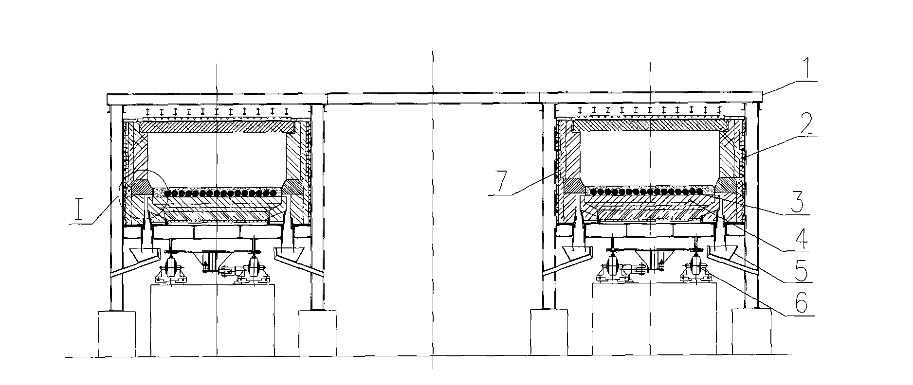
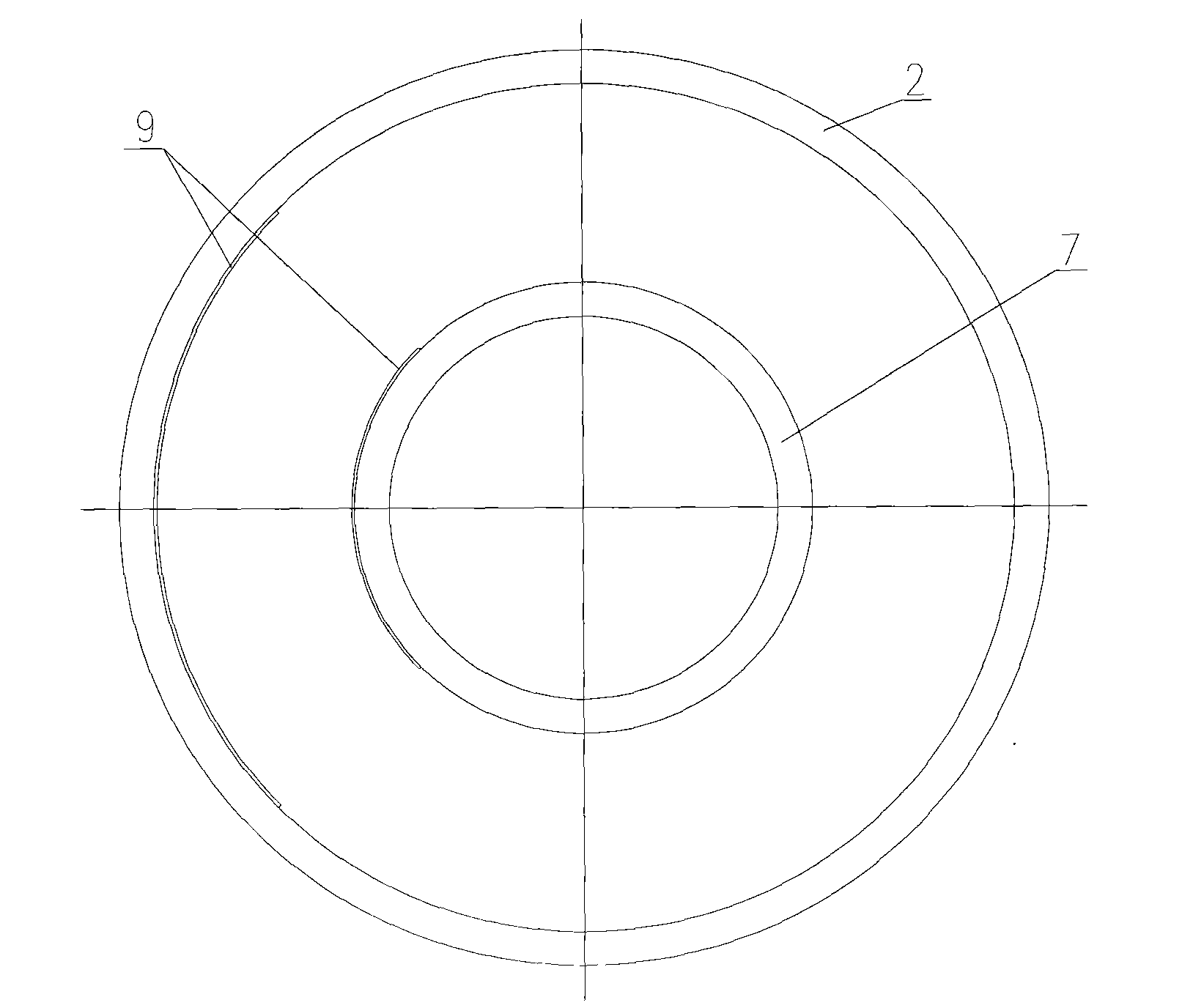
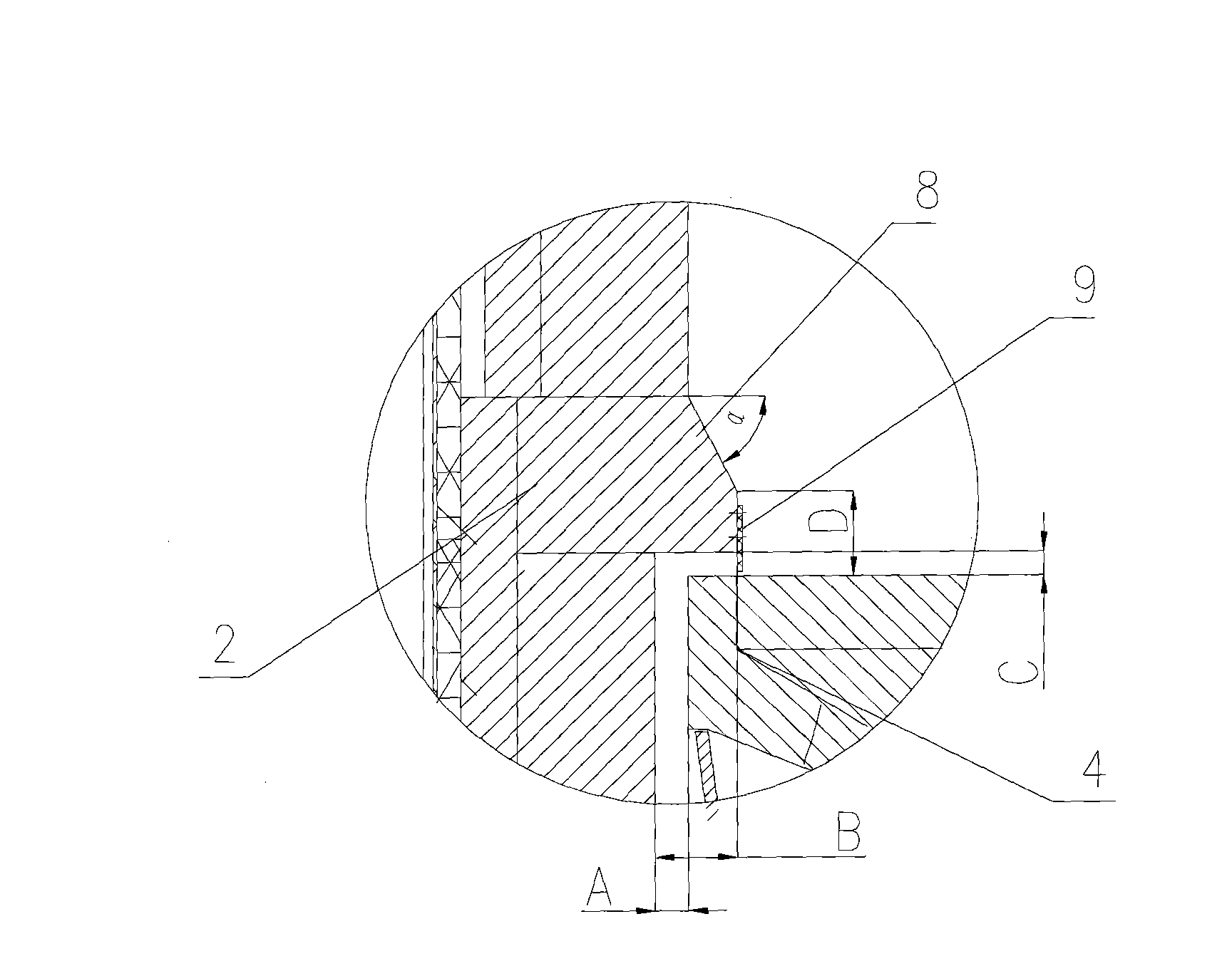
[0023] Such as figure 1 , figure 2 with image 3 Shown is a ring-shaped reduction furnace with no material leakage at the bottom of the furnace, including a furnace frame 1, an outer furnace wall 2, a furnace bottom 4, a water seal tank 5, a furnace bottom machine 6, an inner furnace wall 7, and heat-resistant rubber 9. Such as figure 1 As shown, the outer furnace wall 2 and the inner furnace wall 7 are arranged in the furnace frame 1, an annular furnace is formed between the outer furnace wall 2 and the inner furnace wall 7, the furnace bottom 4 is arranged at the bottom of the annular furnace, and the furnace bottom machinery 6 is arranged Below the furnace bottom 4, the furnace bottom machine 6 can drive the furnace bottom 4 to make a circular motion in the annular furnace. The bottom of the outer furnace wall 2 and the furnace bottom 4 is provided with a water seal groove 5 , and the bottom of the inner furnace wall 7 and the furnace bottom 4 is provided with a water s...


PUM

PropertyMeasurementUnit
thicknessaaaaaaaaaa

Abstract

The invention discloses an annular reduction furnace capable of not leaking material at furnace bottom. The annular reduction furnace comprises a furnace frame, an outer furnace wall, a furnace bottom, a water seal tank, a furnace bottom mechanism and an inner furnace wall, a circle of humps is respectively provided at the part of the inner and outer furnace walls above the furnace bottom, the humps and the furnace bottom coincide partially along the horizontal direction, and a certain gap is formed between the humps and the furnace bottom along the vertical direction. The annular reduction furnace capable of not leaking material at furnace bottom sets a leakage-proof structure in the inner and outer furnace walls, and the leakage-proof structure can not hinder the rotation of the furnacebottom and can effectively prevent the material from entering the water seal tank in the spreading process and the roasting and reduction process so as to reduce the cleaning work of the water seal tank.

Description

technical field [0001] The invention relates to an annular reduction furnace, in particular to an annular reduction furnace with no material leakage at the bottom of the furnace. Background technique [0002] Annular reduction furnace is a new reduction equipment with an annular furnace and a rotatable hearth, so it is also named rotary hearth furnace (RHF). It is transplanted from the steel rolling ring furnace. Its raw materials are carbon-containing pellets and mixtures. It is very versatile. [0003] 1.1 Convert to direct restore or pre-restore device [0004] 1. Direct reduction equipment: high-grade iron ore fines and low-ash coal are used to produce metal pellets with high metallization rate for power supply furnaces. [0005] 2. Pre-reduction equipment for smelting reduction: the products obtained from low-grade iron ore powder and coal need to undergo final reduction, melting, separation of slag and iron to obtain pig iron. [0006] 3. To deal with iron-contain...

Claims


Application Information

Patent Timeline
Patent Type & Authority Applications(China)
IPC IPC(8): F27B9/04F27B9/16F27B9/30
Inventor 顾玲李国良张允茂
Owner 顾玲
Why Eureka
Try Eureka