Supercharge Your Innovation With Domain-Expert AI Agents!

Calibration circuit of RC filter and method

A technology for calibrating circuits and calibration methods, which is applied in the direction of electrical components, impedance networks, multi-terminal pair networks, etc., can solve problems such as low power consumption, difficulty in circuit calibration to ensure high precision, and inability to calibrate changes in capacitance and resistance values ​​in real time, so as to improve Calibration accuracy, effect of avoiding interference

Active Publication Date: 2011-10-05
豪威国际控股有限公司
View PDF0 Cites 0 Cited by
  • Summary
  • Abstract
  • Description
  • Claims
  • Application Information

AI Technical Summary

Problems solved by technology

This method has the advantages of low power consumption and little interference to the circuit, but it cannot real-time calibrate the change of the capacitance and resistance value caused by the environment change during the working process of the circuit.
[0003] Traditional calibration schemes use a multivibrator to generate an RC-related clock frequency f = 1 RC ( 1 + Δ ) , Δ is the hysteresis error of the hysteresis comparator inside the multivibrator. Since this error also changes with the working environment and manufacturing deviation, it is difficult to ensure high accuracy in circuit calibration

Method used


Image

  • Calibration circuit of RC filter and method
  • Calibration circuit of RC filter and method
  • Calibration circuit of RC filter and method

Examples


Embodiment 1

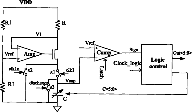
[0022] see figure 1 , The present invention discloses a calibration circuit for an RC filter, the RC filter includes a resistor R and a capacitor C, one end of the RC filter is connected to a power supply with a voltage of VDD, and the other end is grounded. The circuit includes an amplifier, a comparator, and a controller.

[0023] The output terminal of the amplifier is connected between the resistor R and the capacitor C, the first input of the amplifier is divided into a voltage of VDD / 2 (the voltage Vref=VDD / 2 of the first input of the amplifier), and the second input of the amplifier is connected to Enter one end of the resistor R (the voltage of the second input of the amplifier V 1 ≈ Vref = 1 2 VDD ). The method for the first input of the amplifier to divide the voltage into VDD / 2 can be as follows: set two resistors with the same resistance value in series, and generate a ref...

Embodiment 2

[0033] The essence of RC calibration is to ensure that the RC product of the circuit remains unchanged by adjusting R, C or both under different working environments and different manufacturing process conditions. Only C is adjusted alone in the present invention.

[0034] see figure 1 , the specific circuit implementation of the present invention is as figure 1 shown. Divide the voltage of the power supply through the resistor to get Vref = 1 2 VDD , Amplifier Amp is connected with buffer buffer, V 1 ≈ Vref = 1 2 VDD , Therefore, the current flowing through the resistor R is the charging current of the capacitor I ch arg e ≈ VDD 2 R . After charging ...


PUM


Abstract

The invention discloses a calibration circuit of an RC filter and a method. The calibration circuit comprises an amplifier, a comparator and a controller, wherein, the output end of the amplifier is connected between a resistance R and a capacitance C, the voltage of a first input of the amplifier is VDD / 2, and a second input of the amplifier is connected with one end of the resistance R; two inputs of the comparator respectively obtain the voltage Vref of the first input of the amplifier and the charging voltage Vcap of the capacitance C; after the capacitance C is charged with constant current for time T, a comparison result is sent to the controller; the controller adjusts the capacitance C according to the comparison result of the comparator; if Vcap is more than Vref, the controller turns the capacitance C up; if Vcap is smaller than Vref, the controller turns the capacitance C down. The invention directly adopts a voltage comparison method to obtain charging voltage by charging the capacitance, compares the voltage with the reference voltage and adjusts capacitance value according to results, and the final convergence result is T=RC. The calibration precision of the invention directly depends on the maladjustment of the comparator, and can be improved to the utmost.

Description

technical field [0001] The present invention relates to a calibration circuit, in particular to a calibration circuit for an RC filter; in addition, the present invention also relates to a calibration method for the calibration circuit. Background technique [0002] Active RC filters are widely used in analog integrated circuits because of their good linearity and simple implementation. However, in modern semiconductor manufacturing processes, there may be large deviations in both capacitors and resistors, so they must be calibrated for RC. In traditional calibration, using a clock comparison scheme will also affect the overall calibration effect due to the accuracy of the RC multivibrator. In addition, in the past, the calibration circuit was calibrated once during the power-on process of the chip, and then the calibration module stopped working. This method has the advantages of low power consumption and little interference to the circuit, but it cannot real-time calibrat...

Claims


Application Information

Patent Timeline
IPC IPC(8): H03H7/06
Inventor 邓敏
Owner 豪威国际控股有限公司
Features
  • R&D
  • Intellectual Property
  • Life Sciences
  • Materials
  • Tech Scout
  • Unparalleled Data Quality
  • Higher Quality Content
  • 60% Fewer Hallucinations
Learn More