
Inner lining structure of cathode molten pool for aluminum electrolytic cell

An aluminum electrolytic cell and electrolytic cell technology are applied in the field of the lining structure of the cathode molten pool of the aluminum electrolytic cell, which can solve the problems of increased electrolyte pole distance, increased voltage drop at the bottom of the tank, increased horizontal current, etc., and achieves uniform vertical current distribution, The effect of reducing the voltage drop at the bottom of the tank and reducing the horizontal current

Inactive Publication Date: 2010-03-03
高德金
View PDF8 Cites 6 Cited by
  • Summary
  • Abstract
  • Description
  • Claims
  • Application Information

AI Technical Summary

Problems solved by technology

[0005] 1. The aluminum liquid in the electrolytic cell is placed on the upper surface of the cathode carbon block. The temperature difference between the upper and lower parts of the cathode carbon block in the electrolytic cell is large, and the overall thermal balance of the cathode lining is difficult to achieve, resulting in a high resistance of the cathode carbon block itself. The bottom voltage drop increases;
[0006] 2. The aluminum liquid as the cathode conductor in the molten pool of the electrolytic tank only contacts the upper surface of the inner lining of the cathode carbon block, and the conductive area of ​​the cathode carbon block is small, resulting in low conductivity efficiency of the overall structure of the cathode carbon block lining, and it is difficult to increase the electrolytic current density ;
[0007] 3. The connection between the bottom of the cathode carbon block of the electrolytic cell and the cathode steel rod is combined by paste and tamping. Due to the different physical and chemical properties of the materials, the voltage drop at the bottom of the cathode cell is too high;
[0008] 4. Leakage of molten aluminum and electrolyte is likely to occur in the joint between the two carbon blocks; resulting in the fusing of the cathode steel rod placed at the bottom of the cathode carbon block and the occurrence of leakage accidents. Not only the tamping process is complicated, but also the service life of the tank cathode lining is short
[0009] 5. The upper surface of the cathode carbon block of the electrolytic cell is set as a horizontal plane. During the production process, the aluminum liquid on the upper part of the electrolytic cell cathode lining will generate a magnetic swirl flow of the aluminum liquid under the action of a magnetic field, resulting in the setting of the electrolyte pole distance increase, the cell voltage setting increases, resulting in an increase in the power consumption of the electrolytic aluminum process
[0010] 6. Due to the limitation of the structure and size of the cathode carbon block and cathode steel rod, the lengthwise arrangement of the cathode carbon block in the electrolytic cell can be arranged vertically to the direction of the large busbar. In the existing cathode carbon Under the construction method of blocks and cathode steel rods, the expansion of electrolyzer capacity can only be expanded along the long direction of the large busbar, and its expansion in the width direction is limited
[0011] 7. Since the output conduction of the cathode steel rod and the cathode carbon block and the connection end of the large busbar are arranged outside the steel shell on the side of the electrolytic cell, the cathode carbon block is in the electrolytic cell and is arranged horizontally from the inside to the outside to conduct electricity outwards, resulting in The vertical current distribution in the electrolytic cell is unevenly conducted, the horizontal current increases, and the current efficiency decreases

Method used


Image

  • Inner lining structure of cathode molten pool for aluminum electrolytic cell
  • Inner lining structure of cathode molten pool for aluminum electrolytic cell
  • Inner lining structure of cathode molten pool for aluminum electrolytic cell

Examples


Embodiment Construction

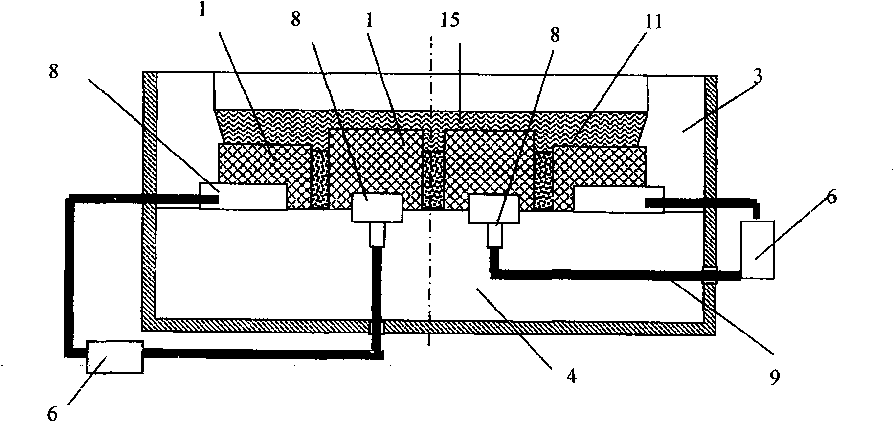
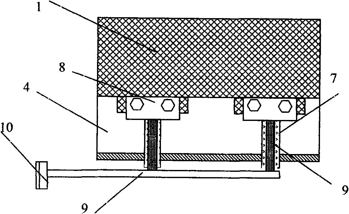
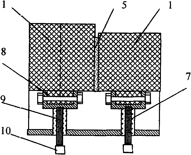
[0038] The lining structure of the cathode molten pool of the aluminum electrolytic cell is improved on the basis of the structure and materials of the cathode molten pool lining of the aluminum electrolytic cell currently in use, and its construction and masonry process can still be based on the current general use of the cathode molten pool lining of the aluminum-aluminum electrolytic cell According to the requirements and standards of the structure, the lining structure of the cathode molten pool of the aluminum electrolytic cell is composed of the electrolytic cell steel shell 2, the bottom insulation material layer 4, the side furnace wall 3, the cathode carbon block 1, the carbon metal cathode conductive connection line and the cathode The large busbar 6 and other components are constructed of materials, and its characteristic is that no cathode cathode steel rod groove is provided at the bottom of the cathode carbon block 1, and no cathode steel rod is provided at the bot...


PUM


Abstract

The invention relates to an inner lining structure of a cathode molten pool for an aluminum electrolytic cell, which eliminates a steel bar groove at the bottom of a cathode carbon block, a cathode steel bar and ramming paste of a steel bar and reduces the voltage drop at the groove bottom; a cathode conductive line is arranged in a heat-preservation and anti-leakage layer at the bottom of the cathode carbon block, the cathode carbon block adopts a sectional mesh point type connection conductive method, so that the vertical current distribution of the aluminum electrolytic cell is more uniform, and the horizontal current is reduced; cathode inner lining conductive carbon blocks are arranged in the furnace walls at the two opposite sides in a multidirectional and sectional arrangement manner, therefore, not only the conditions are created for the widening design of the aluminum electrolytic cell and the diversification of the cathode structure, but also a possibility for implementing the diversified structure of the cross section of the cathode carbon block is provided, and the constructive cost of the electrolytic cell is favorable for reduction; and the upper surface of the cathode inner lining adopts concave-convex design, or an aluminum liquid magnetic cyclone adjusting block is constructed, therefore, the horizontal fluctuation between the aluminum liquid and the electrolyte interface surface can be reduced, the effects of reducing the electrolytic polar distance and setting the low voltage are achieved, and the purpose of reducing the power consumption for electrolyticaluminum production is achieved.

Description

technical field [0001] The cathode molten pool lining structure of aluminum electrolytic cell is mainly used in the construction of prebaked aluminum electrolytic cell and the production of electrolytic aluminum. Background technique [0002] The current general-purpose aluminum electrolytic cell cathode molten pool lining structure is composed of electrolytic cell steel shell, bottom anti-leakage material layer, side furnace wall, tamping paste, and cathode carbon block steel rod group masonry. First, tamp the cathode steel rods with tamping paste in the steel rod groove of the cathode carbon block to form a cathode steel rod group. In the steel shell of the aluminum electrolytic cell, on the anti-leakage material layer of the insulation layer, on the furnace wall at the side of the ring In the middle part, the length direction of the cathode carbon block is vertically arranged along the direction of the large busbar, and the joints between two adjacent cathode carbon block...

Claims


Application Information

Patent Timeline
IPC IPC(8): C25C3/08
Inventor 高德金杨青高伟
Owner 高德金
Learn More