
Novel pilot test setter

A setting machine, a new type of technology, applied in the direction of heating/cooling fabrics, textiles and papermaking, fabric surface trimming, etc., can solve the problems of fabric broken warp and weft, can not effectively achieve rapid cooling, time-consuming, etc., to achieve high-efficiency heating Processing effect

Inactive Publication Date: 2010-03-03
CHINA TEXTILE ACAD JIANGNAN BRANCH +1
View PDF0 Cites 25 Cited by
  • Summary
  • Abstract
  • Description
  • Claims
  • Application Information

AI Technical Summary

Problems solved by technology

[0002] The traditional pilot-scale setting machine, such as the pilot-scale hot air stenter setting machine, mainly has the following technical defects: 1. The electric heating tube is used for heating, and the electric heating system uses a fan to circulate the hot air in the entire oven. Hot air heats the fabric. This method belongs to the indirect heating method of convection heat transfer. This method has low thermal efficiency, long time consumption, and high energy consumption. It is not suitable for the requirements of multi-variety and small-batch experiments; and the ambient temperature around the machine is high, which is not conducive to experimental operations.
2. The traditional pilot setting machine does not have an overfeed system, which cannot increase or decrease the warp tension of the fabric, so that the fabric weight requirement cannot be achieved.
3. The traditional pilot setting machine adopts the overall expansion system, which cannot be adjusted separately; resulting in no buffer space for the fabric during the expansion process, causing the fabric to easily break warp and weft
4. The oven of the traditional pilot test setting machine is a whole, and the temperature in the box is unique, which cannot realize the continuous processing of the pre-baking baking process
5. The traditional pilot setting machine does not have a cloth cooling system, which cannot effectively achieve rapid cooling

Method used


Image

  • Novel pilot test setter
  • Novel pilot test setter
  • Novel pilot test setter

Examples


Embodiment Construction

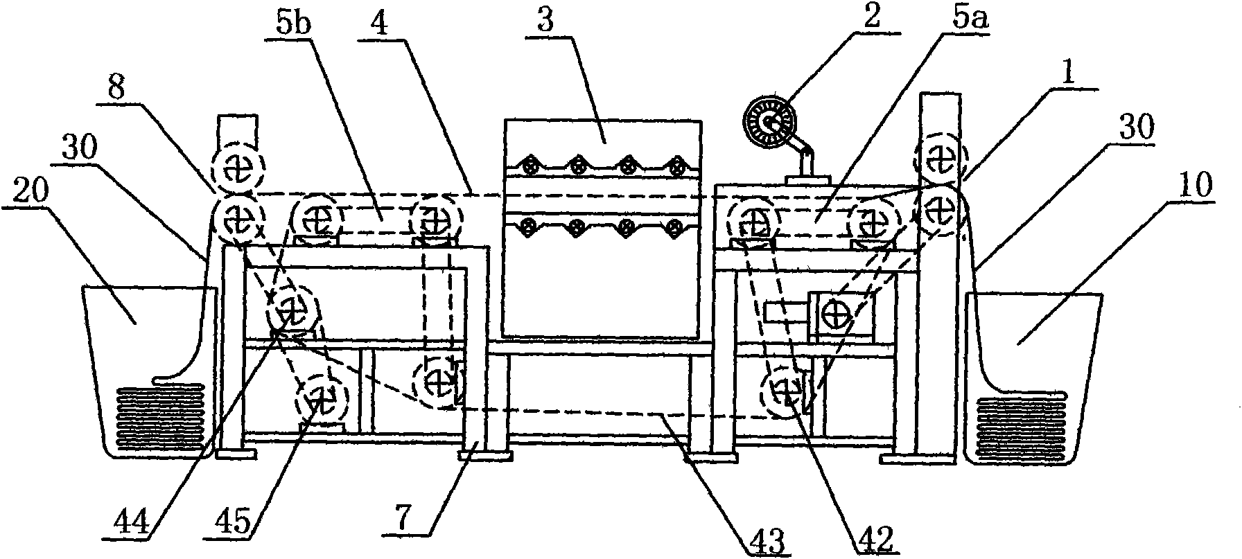
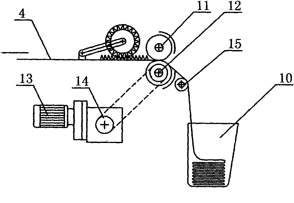
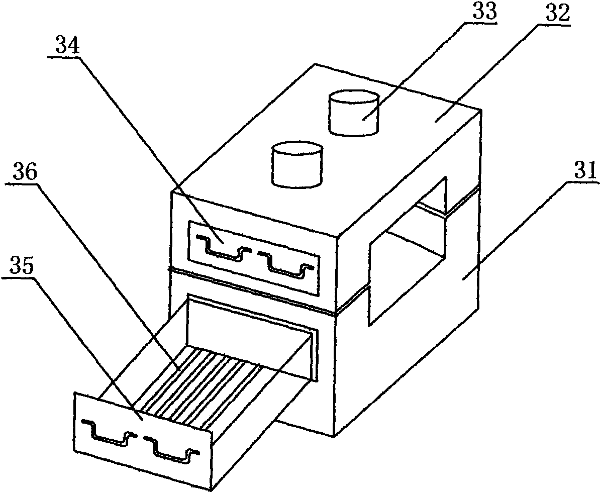
[0027] as attached figure 1 As shown, the new pilot-test setting machine of the present invention includes a frame 7, and the cloth inlet barrel 10 and the cloth outlet barrel 20 are installed at both ends of the frame 7, and are respectively used to place cloth samples 30, and the transmission device 4 is installed on the frame 7, along the conveying device 4 from the cloth inlet end to the cloth outlet end, a cloth feeding and overfeeding transmission device 1, a wool pressing wheel 2, a first expanding device 5a, an infrared oven 3, a second expanding device 5b and an outlet Cloth cooling device 8.

[0028] combine Figure 4 , Figure 5 As shown, the transmission device 4 is installed on the frame 7, connecting the cloth inlet end and the cloth outlet end, including several sprockets 42 installed on the frame 7, and a chain conveyor belt 43 with a needle plate 41 set on the sprocket 42 , sprocket 42 and chain conveyer belt 43 are provided with 2 groups altogether, are le...


PUM


Abstract

The invention discloses a novel pilot test setter which belongs to the technical field of pilot test dyeing equipment and is characterized by comprising a rack, cloth over-feeding actuating devices, sectional type stretch expanders, an infrared oven and a cloth discharge cooling device, wherein a cloth feeding barrel and a cloth discharging barrel are installed at two ends of the rack so as to beused for arranging cloth samples, an actuating device is installed on the rack and used for connecting a cloth feeding end with a cloth discharging end so as to complete the delivery of the cloth samples; the cloth over-feeding actuating devices are sequentially installed along the actuating device from the cloth feeding end to the cloth discharging end, and installed at the cloth feeding end, adjust the linear velocity when the cloth samples enter and realize over-feeding function; the sectional type stretch expanders are installed at two sides of the infrared oven and realize buffering expansion; and the infrared oven is arranged in way of double layer (an upper layer and a lower layer), and conducts infrared drying and setting. The novel pilot test setter integrates the technologies ofheating by far infrared radiation, overfeeding and sectional expansion into a whole, and has the advantages of quick heating rate, short processing time, low energy consumption, high processing efficiency and good finishing effect.

Description

technical field [0001] The invention relates to a sizing machine, specifically a new type of pilot-scale sizing machine integrating far-infrared radiation heating, overfeeding and segmental expansion technology, and belongs to the technical field of pilot-scale printing and dyeing equipment. Background technique [0002] The traditional pilot-scale setting machine, such as the pilot-scale hot air stenter setting machine, mainly has the following technical defects: 1. The electric heating tube is used for heating, and the electric heating system uses a fan to circulate the hot air in the entire oven. Hot air heats the fabric. This method belongs to the indirect heating method of convection heat transfer. This method has low thermal efficiency, long time consumption, and high energy consumption. It is not suitable for the requirements of multi-variety and small-batch experiments; and the ambient temperature around the machine is high, which is not conducive to experimental oper...

Claims


Application Information

Patent Timeline
IPC IPC(8): D06C7/02D06C3/10
Inventor 庄小雄杨国荣李翠萍冯仑仑夏筛根殷玉敏吴荣郎
Owner CHINA TEXTILE ACAD JIANGNAN BRANCH
Learn More