
Shock-insulation support of light free-standing equipment

A technology of shock-isolation bearings and equipment, which is applied in the direction of non-rotational vibration suppression, etc., can solve the problems of not being able to meet the needs of light-weight floating equipment for shock-isolation and vibration reduction, inability to distinguish the degree of damage and failure of components, and the disintegration of floating equipment structures, etc., to achieve Good shock isolation and vibration reduction effect, compact structure, good limit effect

Active Publication Date: 2011-05-25
西安达盛隔震技术有限公司
View PDF0 Cites 0 Cited by
  • Summary
  • Abstract
  • Description
  • Claims
  • Application Information

AI Technical Summary

Problems solved by technology

[0002] The vibration isolation and vibration reduction of light floating equipment is a difficult problem for equipment experts and users at present, especially for precision instruments and measuring instruments, it is necessary to take anti-vibration measures, because the structure of most light floating equipment determines that they cannot increase strength without adding components that control the strength of the entire device
When these devices are subjected to strong vibrations, certain parts on the device may cause loss of precision, rather than damage in the usual sense, and usually the degree of damage and failure of the parts cannot be discerned without special equipment; at the same time, the device may also be damaged For components with low medium-strength reserves, local damage will lead to the disintegration of the entire floating device structure
At present, the shock isolation effect of existing shock isolation devices cannot meet the shock isolation and vibration reduction requirements of light floating equipment.

Method used


Image

  • Shock-insulation support of light free-standing equipment
  • Shock-insulation support of light free-standing equipment

Examples


Embodiment Construction

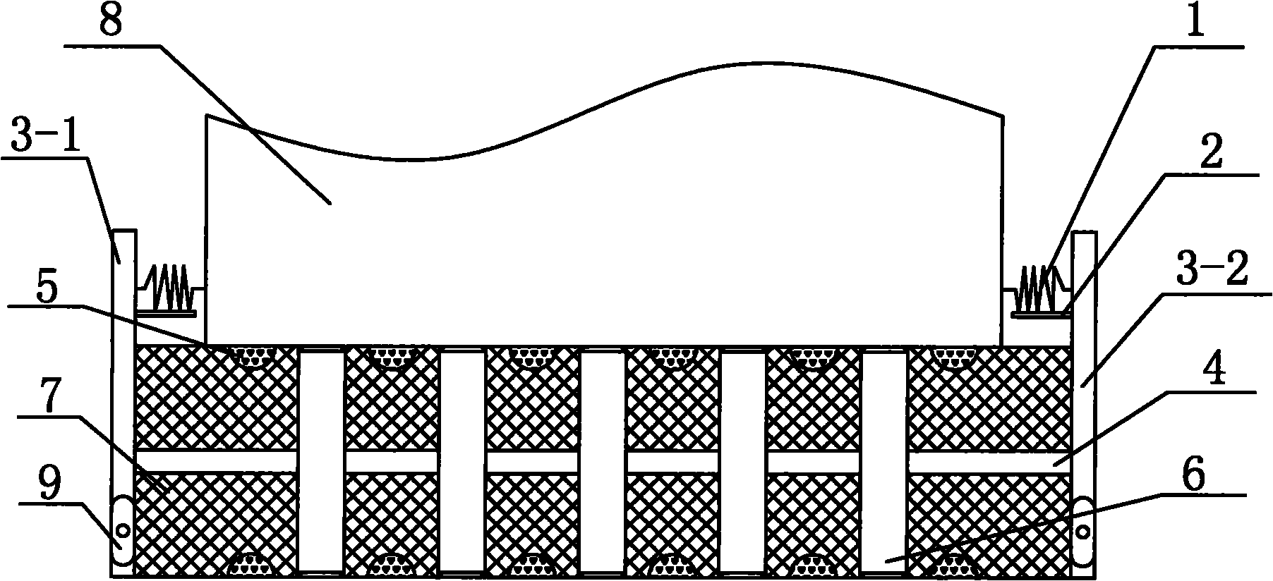
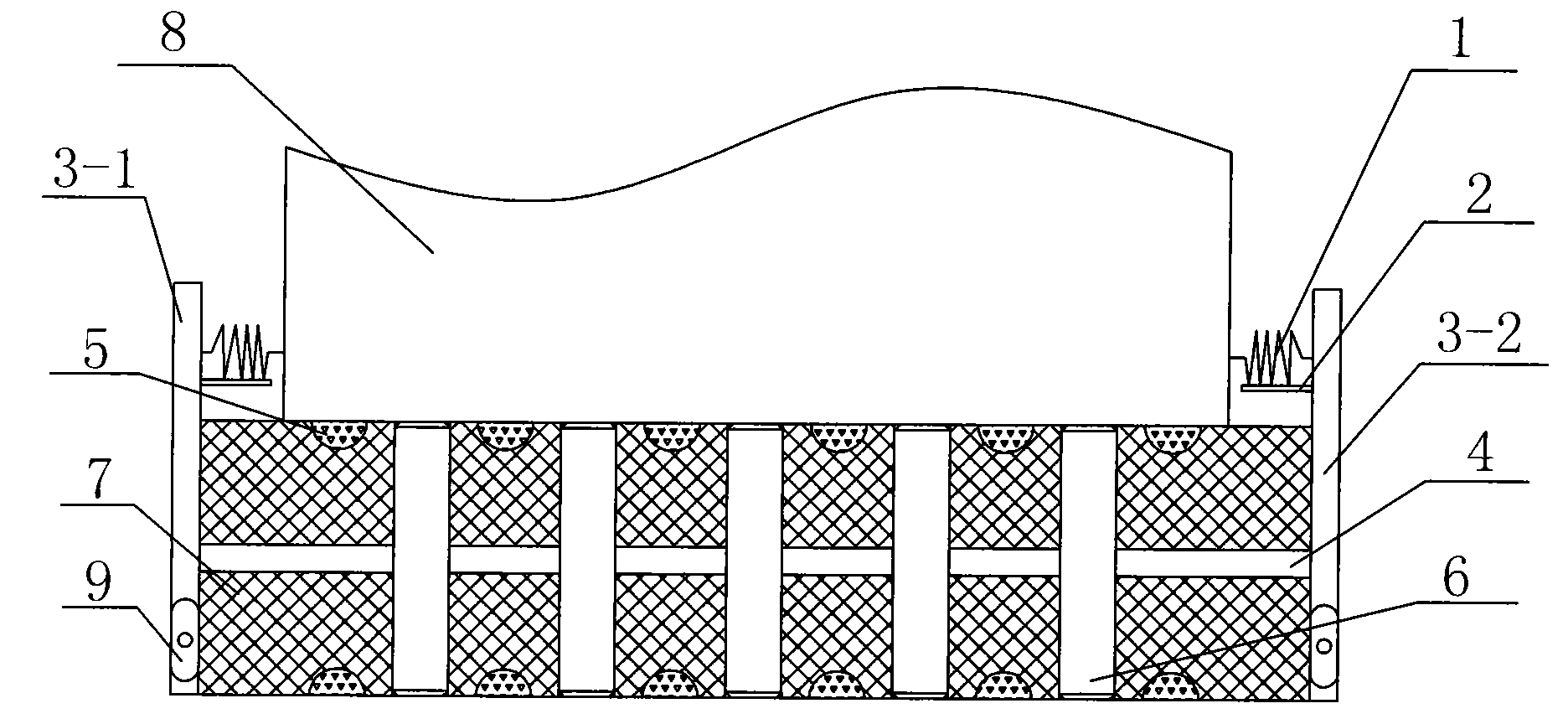
[0024] Such as figure 1 , a shock-isolation support for light-duty floating equipment according to the present invention, comprising two symmetrically arranged limiting plates 1 3-1 and 2 3-2 and set on the limiting plates 1 3-1 and 2 3 The elastic body 7 between -2, the interior of the elastic body 7 is inlaid with a plurality of high damping bodies 6 and a sandwich steel plate 4, and the upper and lower ends of the elastic body 7 are provided with evenly distributed adsorption media 5. Among them, the elastic body 7 has a certain elastic modulus and horizontal stiffness, thereby ensuring the mechanical properties and elastic properties of the support, and the high damping body 6 absorbs vibrations from different directions, increases damping and prolongs the vibration period. On the other hand, in order to limit the effect well, the upper ends of the limiting plate one 3-1 and the limiting plate two 3-2 are provided with telescopic body 1 and support plate 2, and the lower e...


PUM


Abstract

The invention discloses a shock-insulation support of light free-standing equipment, which comprises a limiting plate 1, a limiting plate 2 and a high elastomer, wherein the limiting plate 1 and the limiting plate 2 are symmetrically arranged; the high elastomer is arranged between the limiting plate 1 and the limiting plate 2; a plurality of high damping bodies and an interlayer steel plate are embedded inside the high elastomer; adsorbing mediums are uniformly distributed at the upper end and the lower end of the high elastomer; telescopic bodies and support plates are arranged at the upperends of the limiting plate 1 and the limiting plate 2; and the limiting plate 1 and the limiting plate 2 are both fixedly connected with the high elastomer. The invention has the advantages of compact structure, no installation, good effect of shock-insulation and shock damping and good limiting effect.

Description

technical field [0001] The invention belongs to the technical field of shock-isolation supports, and in particular relates to a light-weight floating device shock-isolation support. Background technique [0002] The vibration isolation and vibration reduction of light floating equipment is a difficult problem for equipment experts and users at present, especially for precision instruments and measuring instruments, it is necessary to take anti-vibration measures, because the structure of most light floating equipment determines that they cannot increase strength without adding components that would control the strength of the entire device. When these devices are subjected to strong vibrations, certain parts on the device may cause loss of precision, rather than damage in the usual sense, and usually the degree of damage and failure of the parts cannot be discerned without special equipment; at the same time, the device may also be damaged For components with low medium-str...

Claims


Application Information

Patent Timeline
Patent Type & Authority Patents(China)
IPC IPC(8): F16F15/04
Inventor 盛明勇王莫莲
Owner 西安达盛隔震技术有限公司
Learn More