Valve element assembly

A spool assembly and spool technology, applied in multi-way valves, valve devices, engine components, etc., can solve problems such as limited water pressure, difficult design and processing, and large force on the force arm parts of the spool, to achieve Reduces the possibility of water leakage, simple design and processing, and the effect of reducing the angle of rotation

Inactive Publication Date: 2010-03-03
文晓锋
View PDF0 Cites 10 Cited by
  • Summary
  • Abstract
  • Description
  • Claims
  • Application Information

AI Technical Summary

Problems solved by technology

So the faucet body or other parts must contact the water flow, making the design and processing of these parts quite difficult
[0004] 2. The rotation torque is too long, so that the arm parts of the spool are under too much force and are easily damaged
Can withstand water pressure very limited
[0006] 4. The two water inlet holes of the water inlet valve are located side by side, so that the rotation angle of the moving valve is too large, and the valve is easy to wear
Gasket aging is prone to water leakage

Method used


Image

  • Valve element assembly
  • Valve element assembly
  • Valve element assembly

Examples


no. 3 example

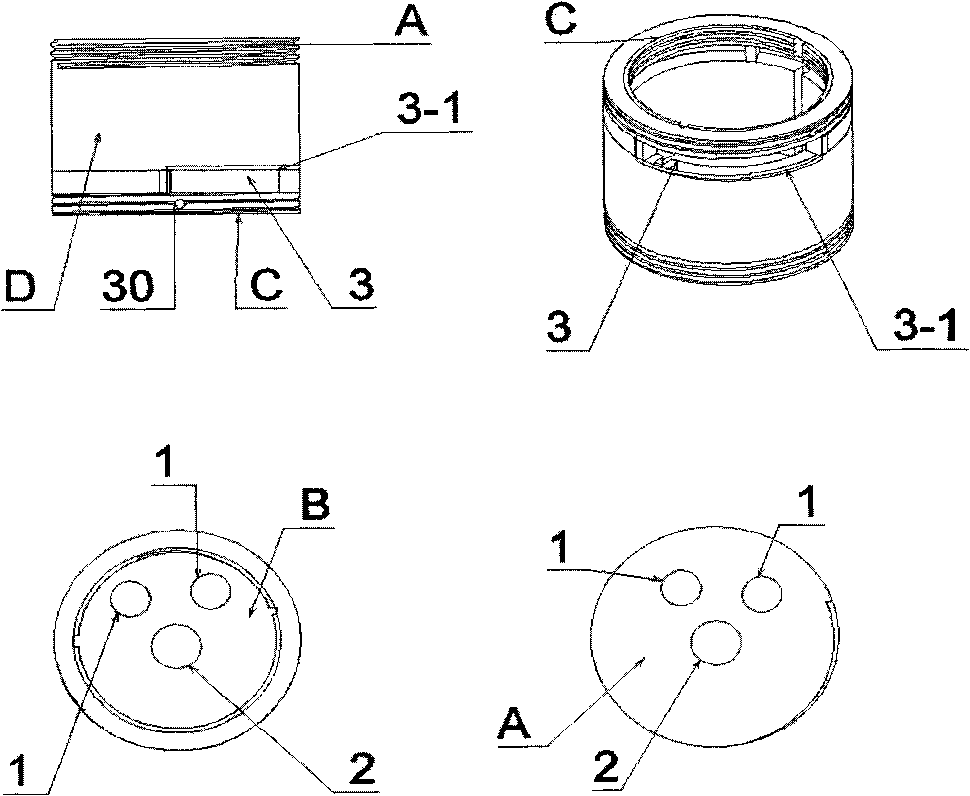
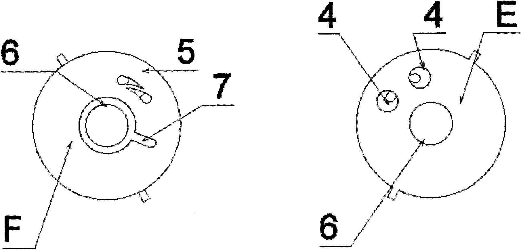
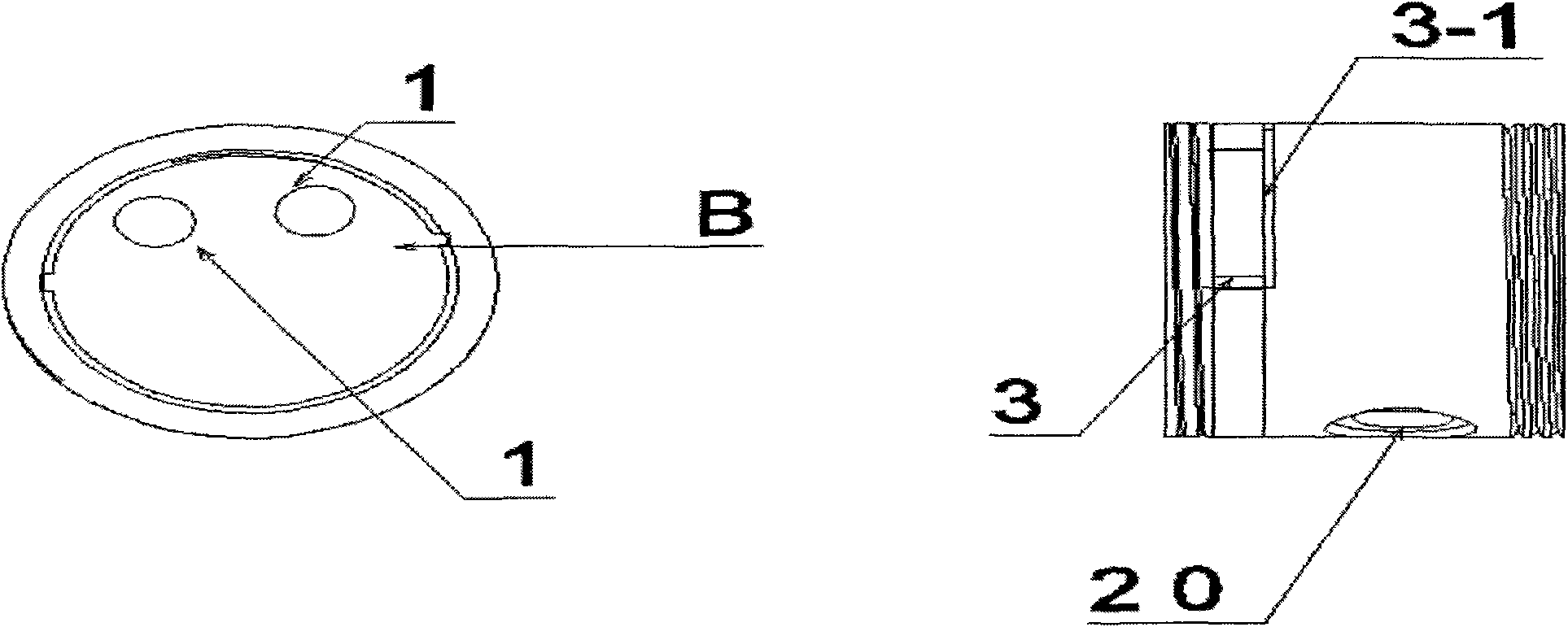
[0058] The third embodiment (explaining that the outer diameter of the movable valve plate is a shaft type---B-1 formula). The movable valve plate c-3 moves along the axis of the inner ring of the limit ring s with its own outer diameter as the axis. The groove 38 of its bottom surface G-3 seals and fits and slides to control the water flow above the two water inlet holes 5 on the top surface F of the water inlet valve plate (b-1). The inner ring of the limit ring s and the side of the movable valve plate c-3 fit and slide. The hollow boss J-3 on the top surface H-3 of the movable valve plate c-3 is embedded in the central hole 51 of the water outlet valve plate d-3, and the two valve plates are sealed and slid. The water flow passes through the groove 38 of the movable valve plate c-3 and the water outlet hole 48 successively, the central hole 51 of the water outlet valve plate d-3, and the spool pressing cap f-3 connection hole 52 flows out of the spool. A flat gasket q-4 ...


PUM


Abstract

The invention relates to a novel valve element assembly. The valve element assembly alone has main functions such as the water controlling function, the water guiding function, the support function and the like of a water faucet, thereby enabling the shell (the body) of the faucet to be unnecessary to be in contact with water flow and is used only for configuration decoration. The valve element assembly mainly comprises a pedestal, valve plates, a valve element pressing cap and an extended water guiding hose, and optionally comprises an added component (a filter, an electric heater or the like) at a water outlet end of the valve element assembly or the like. The valve plates (or together with the valve element pressing cap) control the water flow and form an independent sealed water channel, and the functions of switching and changing the water flow can be realized by only using movable valve plates to seal a switching rotating shaft between water inlet valve plates and water outlet valve plates. The water flow is guided to the faucet through the connection of the extended water guiding hose and a water outlet of the valve element assembly (or a water outlet of the added component)and flows out. To add multiple functions and meet other design requirements, the added component (such as, the filter, the electric heater or the like) can be additionally connected to the water outlet end of the valve element assembly. Then a water outlet of the same type (a lug boss type water outlet or a connection hole type water outlet) is designed on the added component, which facilitates the connection with the extended water guiding hose. The valve plates are designed into tri-dimensional valve plates, planar valve plates and double acting valve plates, all of which are applicable toa bathroom faucet and a basin faucet.

Description

technical field [0001] The invention belongs to a valve core assembly of a mechanical faucet product. Background technique [0002] The faucet spools disclosed in the market generally just switch the water flow. There are several defects in this product: [0003] 1. Since the valve core only switches the water flow, it has no diversion function. Therefore, the faucet body or other parts must contact the water flow, making the design and processing of these parts quite difficult. [0004] 2. The rotational torque is too long, so that the moment arm parts of the spool are under too much force and are easily damaged. [0005] 3. Plastic housing parts for ceramic chips. Water pressure is very limited. [0006] 4. The two water inlet holes of the water inlet valve plate are located side by side, so that the rotation angle of the moving valve plate is too large, and the valve plate is easy to wear. [0007] 5. The water inlet and outlet of the valve core are connected with t...

Claims


Application Information

Patent Timeline
Patent Type & Authority Applications(China)
IPC IPC(8): F16K11/08
Inventor 文晓锋
Owner 文晓锋
Why Eureka
Try Eureka