Heat dissipating device for LED light source with embedded endoscope

A technology of LED light source and heat dissipation device, which is applied to cooling/heating devices of lighting devices, endoscopes, light sources, etc., can solve problems such as unsatisfactory heat dissipation effects, and achieve long-term stable work, satisfactory use effects, and extended use The effect of longevity

Inactive Publication Date: 2010-03-03
苏州工业园区广福汽保机电设备有限公司
0 Cites 2 Cited by

AI-Extracted Technical Summary

Problems solved by technology

Although the device is small in size and compact in...

Abstract

The invention provides a heat dissipating device for an LED light source with an embedded endoscope, which comprises a radiator and a direct-current fan, wherein the radiator is an aluminum hollow cylinder with a snowflake-shaped outer wall; the LED light source is fixed with the front end of the aluminum hollow cylinder via heat conducting glue; the back end of the aluminum hollow cylinder is provided with a mounting pillar in a projecting way; and the 12V direct-current fan is connected and fixed to the mounting pillar. When the heat dissipating device is used, heat of the LED light source is transmitted in time via the aluminum hollow cylinder, and the fan blows strong wind to the aluminum hollow cylinder. Therefore, the heat dissipating device achieves satisfactory continuous heat dissipation effect, effectively ensures that the junction temperature of the LED is lower than the specified value, ensures the LED to run stably for a long time, and is worthy of popularization and application.

Application Domain

Point-like light sourceSemiconductor/solid-state device details +5

Technology Topic

Hollow cylinderEngineering +6

Image

  • Heat dissipating device for LED light source with embedded endoscope
  • Heat dissipating device for LED light source with embedded endoscope

Examples

  • Experimental program(1)

Example Embodiment

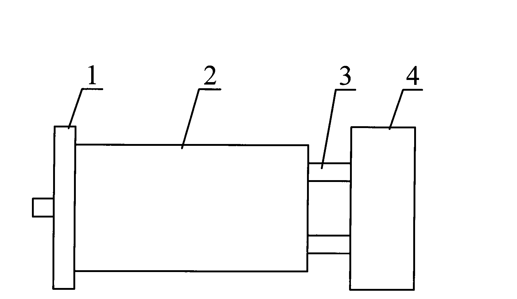
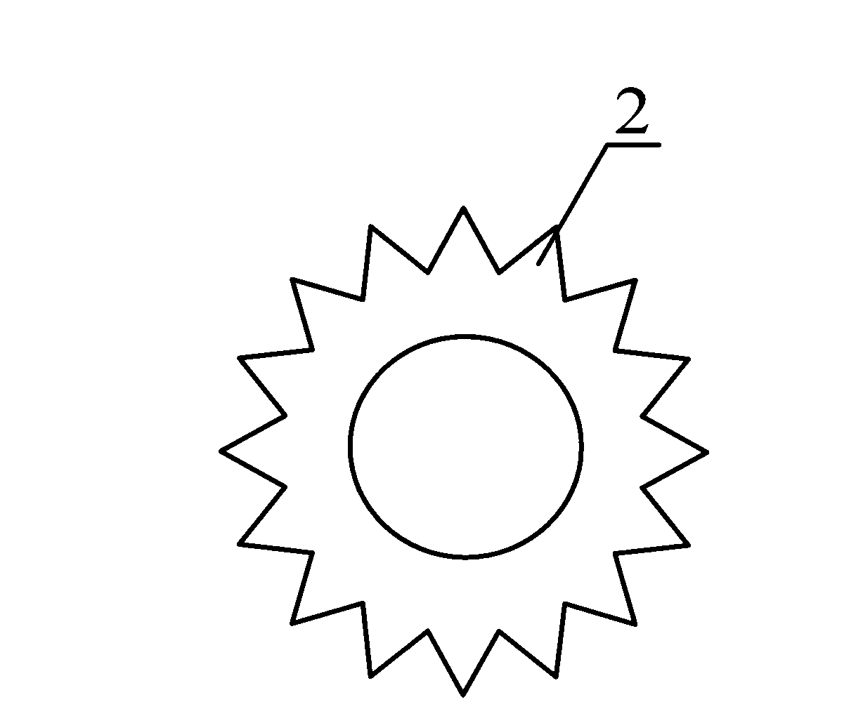
[0019] Such as figure 1 As shown, the heat dissipation device of the built-in LED light source of the endoscope mainly includes a heat sink and a DC fan 4. The heat sink is an inner hollow cylinder 2, such as figure 2 , The outer wall of the inner hollow cylinder 2 is a snowflake shape, and the material of the inner hollow cylinder 2 is aluminum; the LED light source 1 is fixed to the front end of the inner hollow cylinder 2 by thermally conductive glue, and the rear end of the inner hollow cylinder 2 is convex A mounting post 3 is provided, and a fixed DC fan 4 is connected to the mounting post 3, and the DC fan 4 is a 12V DC fan.
[0020] The use of thermally conductive glue between the LED light source 1 and the aluminum inner hollow cylinder 2 can not only quickly transfer the heat emitted by the LED light source 1 to the aluminum inner hollow cylinder 2, but also install and fix the LED light source 1 after the thermal conductive glue has solidified , Reducing additional LED fixtures. The aluminum inner hollow cylinder 2 is adopted, the outer wall of which is snowflake-shaped, and the largest heat dissipation area is achieved in the smallest volume. Equipped with a 12V DC fan for heat dissipation. Compared with a 5V DC fan for heat dissipation, the advantage is that it not only increases the air flow per unit time, but also reduces the circuit for converting the 12V power supply to the 5V power supply, reducing the cost and reducing the size.
[0021] In specific applications, the heat emitted by the LED light source 1 is quickly transferred to the aluminum inner hollow cylinder 2 for storage, and the 12V DC fan 4 blows the aluminum inner hollow cylinder 2 strongly, so that the heat is quickly dissipated, achieving a good Continuous heat dissipation effect.
[0022] In summary, the present invention has a unique design and novel structure, that is, through optimized design, the heat of the LED light source is transmitted through a good heat sink in time, thereby ensuring that the LED junction temperature is less than the specified value, ensuring that the LED works stably for a long time, and extending the LED Service life: It greatly reduces the cost and improves the economic efficiency. It is worthy of widespread application.
[0023] It should be understood that, although the above embodiments have described the present invention in more detail, these descriptions are only illustrative of the present invention, and not a limitation of the present invention. Any invention that does not exceed the essential spirit of the present invention shall fall into Come into the protection scope of the present invention.

PUM

no PUM

Description & Claims & Application Information

We can also present the details of the Description, Claims and Application information to help users get a comprehensive understanding of the technical details of the patent, such as background art, summary of invention, brief description of drawings, description of embodiments, and other original content. On the other hand, users can also determine the specific scope of protection of the technology through the list of claims; as well as understand the changes in the life cycle of the technology with the presentation of the patent timeline. Login to view more.

Similar technology patents

Rustproof lubricating agent

Owner:3M INNOVATIVE PROPERTIES CO

Method for creating internal dumping conditions of strip mine

InactiveCN102966355ATransportation distance is shortExtended service life
Owner:马钢集团设计研究院有限责任公司 +1

Classification and recommendation of technical efficacy words

Why Eureka
Try Eureka