Tri-frequency microwave bandpass filter

A filter and microwave band technology, applied in waveguide devices, electrical components, circuits, etc., can solve the problems that the external impedance matching network is difficult to reach, and there are only two control frequency bands, so as to achieve compact design, convenient circuit processing, and easy integration Effect

Inactive Publication Date: 2010-03-03
EAST CHINA JIAOTONG UNIVERSITY
View PDF0 Cites 15 Cited by
  • Summary
  • Abstract
  • Description
  • Claims
  • Application Information

AI Technical Summary

Problems solved by technology

However, when three or more passbands are to be realized, the tapped input and output structures are used. In order to achieve the external quality factors of the three frequency bands at the same time, it is difficult to achieve the external impedance matching network; and the gap coupling structure can achieve control There are only two frequency bands

Method used


Image

  • Tri-frequency microwave bandpass filter
  • Tri-frequency microwave bandpass filter
  • Tri-frequency microwave bandpass filter

Examples


Embodiment Construction

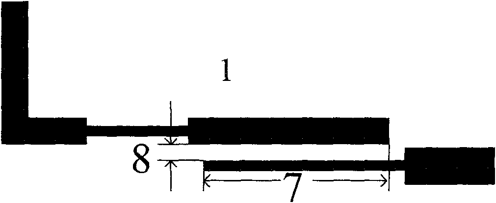
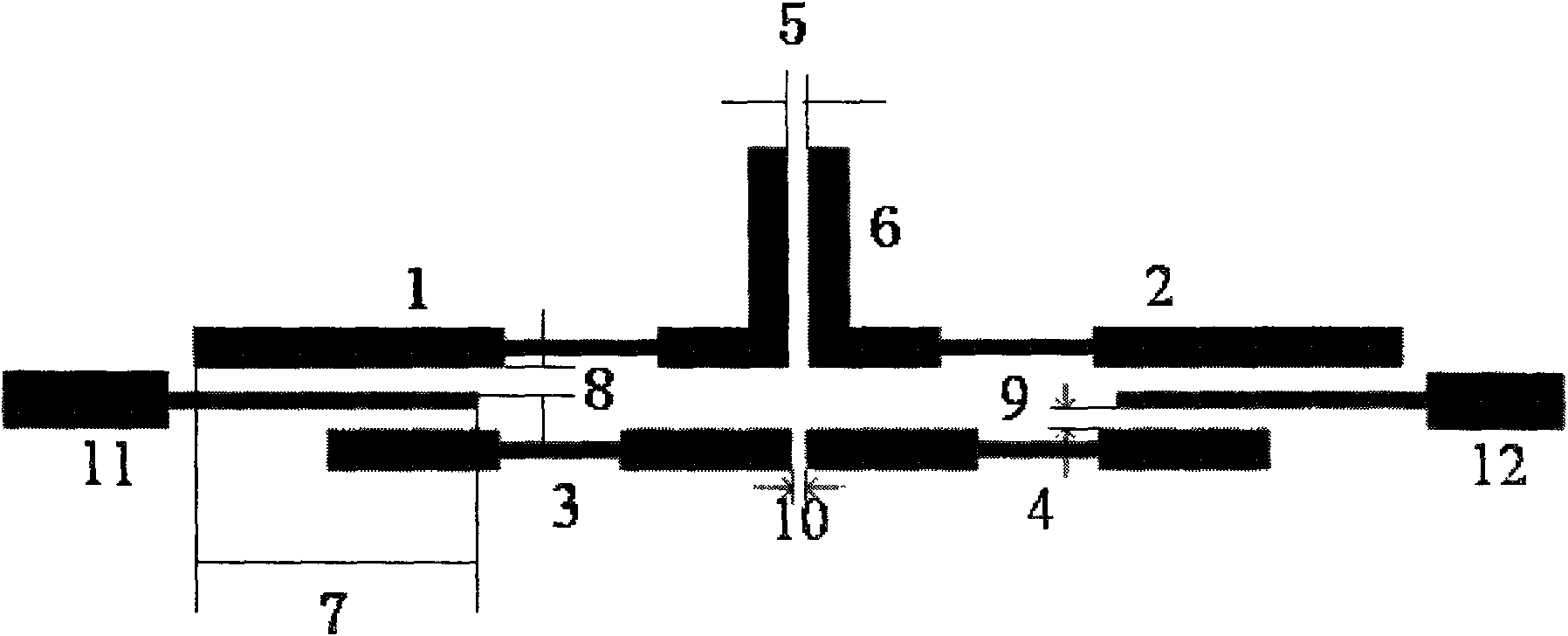
[0016] The triple-frequency microwave bandpass filter of this embodiment adopts a structure composed of an antiparallel coupled line structure and a gap coupled input-output structure, as shown in the attached image 3 shown. In this embodiment, the stepped impedance resonator (1) and the stepped impedance resonator (2) are long stepped impedance resonators, and the stepped impedance resonator (3) and the stepped impedance resonator (4) are short stepped impedance resonators. The distance (5) between the ladder impedance resonators (1) and (2) is 0.25mm, and its overlapping length (6) is 5.6mm; the input-output transmission line (11) or (12) and the resonator (1) or (2 ) overlapping length (7) is 7.7mm, the distance (8) is 0.2mm; the distance (9) between the input and output transmission line (11) or (12) and the ladder impedance resonator (3) or (4) is 0.25mm ; The distance (10) between the ladder impedance resonators (3) and (4) is 0.15mm.

[0017] Signals are input from t...


PUM


Abstract

The invention relates to a tri-frequency microwave bandpass filter which adopts two different groups of stepped inpedance resonators, an anti-parallel coupled line way is adopted between a long-step inpedance resonator (1) and a long-step inpedance resonator (2) of the filter, an end coupling way is adopted between a short-step inpedance resonator (3) and a short-step inpedance resonator (4), andthe input and output adopt clearance coupling. The coupling of the long-step inpedance resonators is utilized to form a first passband and a third passband of the filter, and the coupling of the short-step inpedance resonators forms a second passband of the filter. Three passbands of the filter are formed by utilizing different resonators, the bandwidth of the filter can be effectively controlledby adopting a coupling way; the tri-frequency microwave bandpass filter can be applied to a microwave communication system.

Description

technical field [0001] The invention relates to a triple-frequency microwave band-pass filter adopting a novel coupling structure, which belongs to the technical field of microwave communication equipment. Background technique [0002] As a key device in the communication system, the multi-frequency design of the microwave filter has become a key technology. Usually, a multi-frequency microwave filter is realized by inserting a stop band in a wide pass band, which can be realized by connecting a wide band band pass filter and a narrow band band stop filter in series; or by two different band pass filters In order to achieve the impedance matching of the input and output terminals, it is usually necessary to insert an impedance matching network between the port and the filter. However, the above-mentioned applications are all based on the single-band filter design method, and the external impedance matching network will occupy a larger circuit area and cause greater entry an...

Claims


Application Information

Patent Timeline
Patent Type & Authority Applications(China)
IPC IPC(8): H01P1/20
Inventor 官雪辉王杉
Owner EAST CHINA JIAOTONG UNIVERSITY
Why Eureka
Try Eureka