
Heating furnace structure

A technology of heating furnace and heating tank, which is applied in the direction of distillation and separation, boiling equipment, chemical instruments and methods, etc. It can solve the problems of high requirements for on-site restoration construction, poor overall appearance, and difficult transportation, and achieves unchanged functions and simplified packaging. Head and flange structure, cost saving effect

Active Publication Date: 2012-03-07
XIAN CHANGQING TECH ENG
View PDF0 Cites 0 Cited by
  • Summary
  • Abstract
  • Description
  • Claims
  • Application Information

AI Technical Summary

Problems solved by technology

[0006] (3) Difficult transportation, high requirements for on-site restoration construction
[0007] (4) The structure is bulky and the overall appearance is not good

Method used


Image

  • Heating furnace structure
  • Heating furnace structure
  • Heating furnace structure

Examples


Embodiment Construction

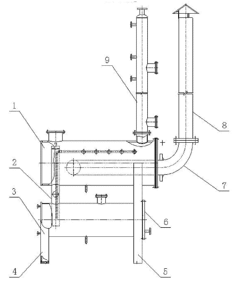
[0025] like figure 1 As shown, the heating furnace structure includes a heating tank 1 and a heat exchange tank 3 connected below the heating tank 1, a liquid-rich rectification column 9 is arranged on the top surface of the heating tank 1, and a flange plate at the end of the heating tank 1 The chimney 8 is connected through the elbow 7, the heat exchange tank 3 is supported by the left support 4 and the right support 5, and the heating tank 1 is connected with the heat exchange tank 3 through the lean liquid rectification column 2 and the extension arm of the right support 5 support; and the left support 4 is connected to the left end surface of the tank body of the heat exchange tank 3, and the right support 5 is connected to the inner side of the flange right end cover 6 of the right end surface of the heat exchange tank 3 tank body.

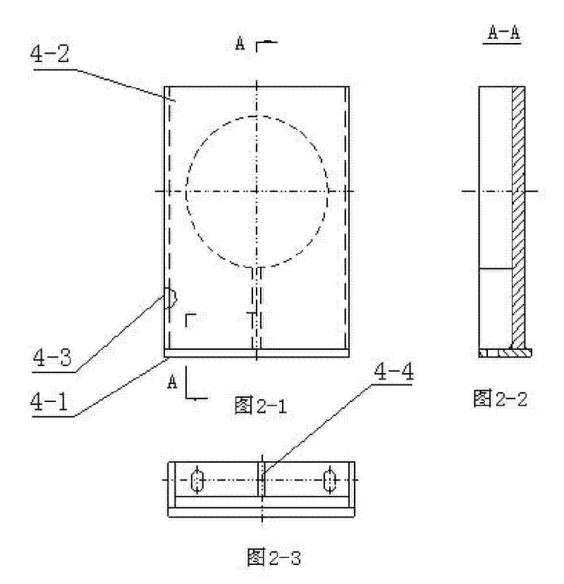
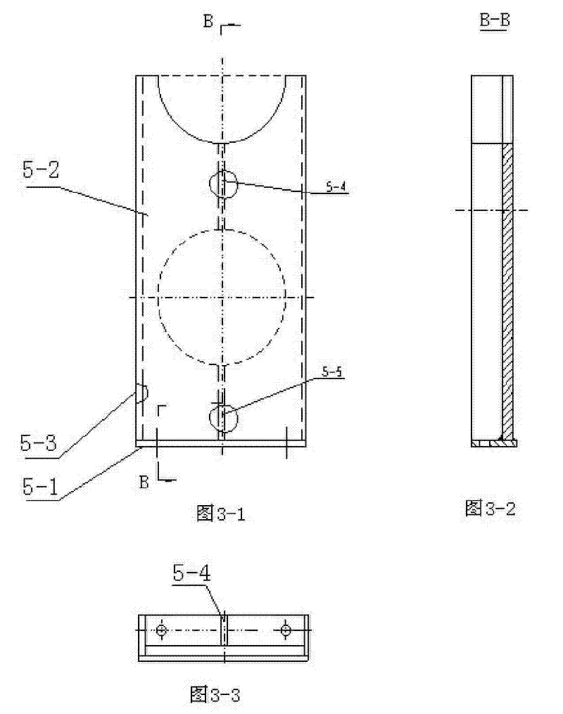
[0026] like figure 2 As shown, the left support 4 is composed of the bottom plate 4-1, the web 4-2, the front and rear side plates 4-3 an...


PUM

PropertyMeasurementUnit
diameteraaaaaaaaaa
thicknessaaaaaaaaaa
diameteraaaaaaaaaa

Abstract

The invention relates to a heating equipment used for petroleum and natural gas and chemical industry and the like, in particular to a heating furnace structure, comprising a heating tank and a heat exchanging tank communicated below the heating tank; the top surface of the heating tank is provided with a rich-liquid rectifying column; and a flange plate at the end part of the heating tank is communicated with a chimney through an elbow. The heating furnace structure is characterized in that the heat exchanging tank is supported by a left support seat and a right support seat, and the heatingtank is supported by a poor-liquid rectifying column communicated with the heat exchanging tank and an extending arm of the right support seat; and the left support seat is connected on the left end surface of a heating tank body, and the right support seat is connected at the inner side of a right end cover of the flange at the right end surface of the heating exchanging tank body. The heating furnace structure has the advantages of strong innovativeness, novel type, reasonable stress, simpleness and practicability, and can simplify the structure, greatly reduce investment and improve marketcompetitiveness.

Description

technical field [0001] The invention relates to a heating device used in petroleum, natural gas and chemical industries, in particular to a heating furnace structure. Background technique [0002] At present, there are two common types of heating and heat exchange equipment used in petroleum, chemical, natural gas purification and other industries: one is horizontal equipment, mainly supported by two saddles; Supports such as seats or outriggers. These two structural forms are widely used, mainly to meet the actual needs of general engineering. [0003] The common double saddle structure that adopts has the following problems: [0004] (1) The structure will become very complicated, with a total of six saddle supports. [0005] (2) In order to meet the sealing requirements of the pipeline, the connection requirements at the two saddles are relatively high. [0006] (3) The transportation is difficult, and the requirements for on-site restoration and construction are high...

Claims


Application Information

Patent Timeline
Patent Type & Authority Patents(China)
IPC IPC(8): B01B1/00B01D3/00
Inventor 李永生何茂林
Owner XIAN CHANGQING TECH ENG
Learn More