Kneading groove in kneading machine

A kneading machine and kneading tank technology, applied in the field of kneading machines, can solve the problems of much longer kneading time and low kneading efficiency of silicone rubber, so as to shorten the kneading time, improve the kneading effect, and increase the shear force. Effect

Inactive Publication Date: 2010-03-10
ZHANGJIAGANG LANHANG MACHINERY
View PDF0 Cites 2 Cited by
  • Summary
  • Abstract
  • Description
  • Claims
  • Application Information

AI Technical Summary

Problems solved by technology

However, in the process of kneading silicone rubber resin powder and other various additives in this kind of kneader, due to the special toughness of silicone rubber (the toughness is much greater than other rubber materials), under the same conditions, a batch of other rubber materials is 8 Kneading can be completed in ~10 minutes, and the kneading time of silicone rubber is much longer; this makes the kneading efficiency of silicone rubber relatively low; if you want to shorten the kneading time of silicone rubber and improve its kneading effect, It is necessary to increase the shear force on the material during the mixing process.

Method used


Image

  • Kneading groove in kneading machine
  • Kneading groove in kneading machine
  • Kneading groove in kneading machine

Examples


Embodiment Construction

[0011] Specific embodiments of the present invention will be described in detail below in conjunction with the accompanying drawings.

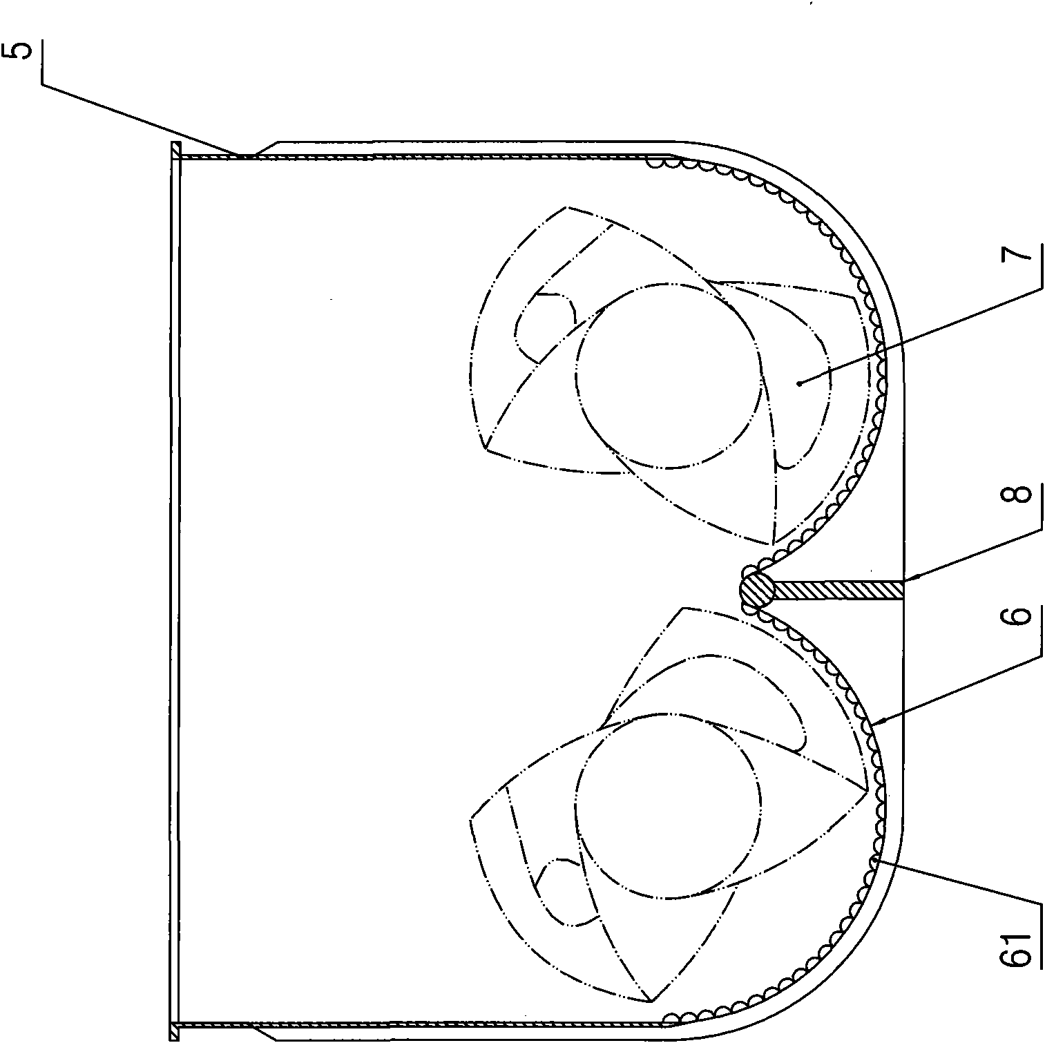
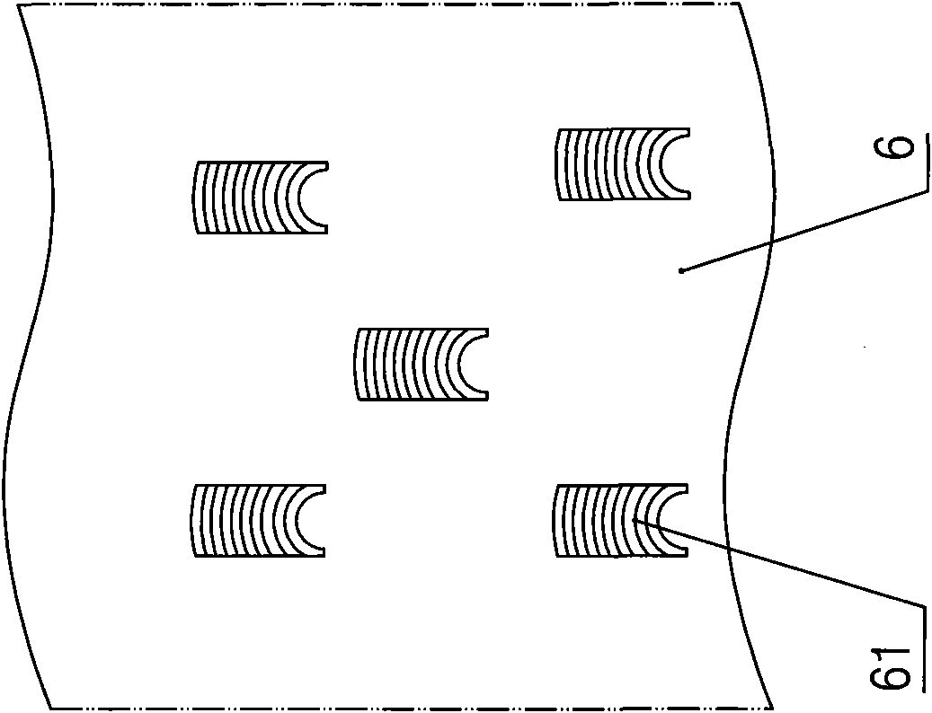
[0012] Such as figure 2 As shown, the kneading tank in the kneader of the present invention includes: a tank wall 5 and a tank bottom 6, and the inner surface of the tank bottom 6 is surfacing with several protrusions 61 for increasing the shear force; and each Multiple lines are arranged on the surface of each protrusion 61 to further increase the shearing force—see image 3 shown.

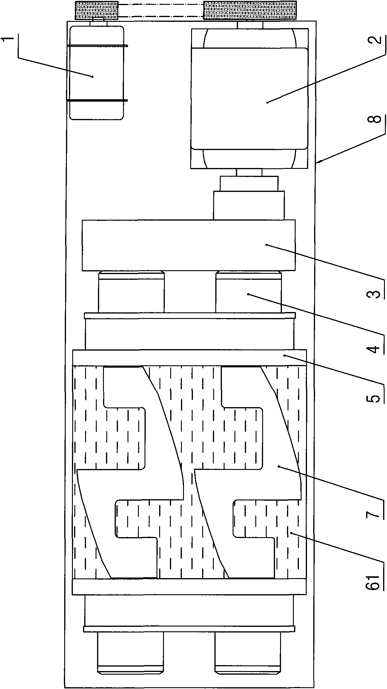
[0013] Such as figure 1 As shown, the kneader provided with the kneading tank of the present invention has the following working process: the motor 1 drives the reducer 2 to rotate, and the reducer 2 drives a pair of gear boxes through the gear box 3 and is respectively arranged in the frame 8 through the bearings 4. The stirring shaft 7 rotates, and the material is squeezed with the tank wall 5 and the tank bottom 6 of the kneading tank under the stirring of...


PUM


Abstract

The invention discloses a kneading groove in a kneading machine for improving shearing force to materials, which comprises a groove wall and a groove bottom, wherein the inner surface of the groove bottom is provided with a plurality of bosses, and a plurality of veins are arranged on the surface of each boss. The inner surface of the groove bottom of the kneading groove is provided with the plurality of bosses to increase the shearing force to the materials so as to achieve the aims of shortening the kneading time of silicone rubber and improving the kneading efficiency of the silicone rubber. In addition, the veins arranged on the surface of each boss can further increase the shearing force to the materials in the process of stirring so as to further shorten the kneading time of the silicone rubber, improve the kneading effect on the silicone rubber, and reduce about 5 percent of the energy consumption.

Description

technical field [0001] The present invention relates to a kneader, in particular to a kneading tank in a kneader. Background technique [0002] As we all know, a kneader usually includes: a kneading tank, a pair of stirring shafts arranged in the kneading tank, and a motor and a reducer for driving the stirring shaft. The kneading tank includes: a tank wall and a tank bottom, a tank The inner surfaces of the walls and the bottom of the tank are very smooth. When in use, put various materials that need to be kneaded in the kneading tank, and the shear force between the stirring shaft and the stirring shaft, and between the stirring shaft and the kneading tank formed by the stirring of the mixed material on the stirring shaft (rotor) Under the action of the mixture, the mixed materials can achieve the purpose of melting, gelling and kneading. However, in the process of kneading silicone rubber resin powder and other various additives in this kind of kneader, due to the speci...

Claims


Application Information

Patent Timeline
Patent Type & Authority Applications(China)
IPC IPC(8): B29B7/22
Inventor 黄振芳
Owner ZHANGJIAGANG LANHANG MACHINERY
Why Eureka
Try Eureka