Structure for supporting a sleeve member in automatic transmission

A technology for automatic transmissions and tubular components, which is applied to vehicle components, components with teeth, transmission parts, etc., and can solve problems such as vibration of tubular components

Active Publication Date: 2010-03-10
JATCO LTD +1
View PDF6 Cites 7 Cited by
  • Summary
  • Abstract
  • Description
  • Claims
  • Application Information

AI Technical Summary

Problems solved by technology

[0004] In the device of this conventional example, the rotational vibration accompanying the rotation of the internal gear is directly transmitted to the conne

Method used


Image

  • Structure for supporting a sleeve member in automatic transmission
  • Structure for supporting a sleeve member in automatic transmission

Examples


Embodiment Construction

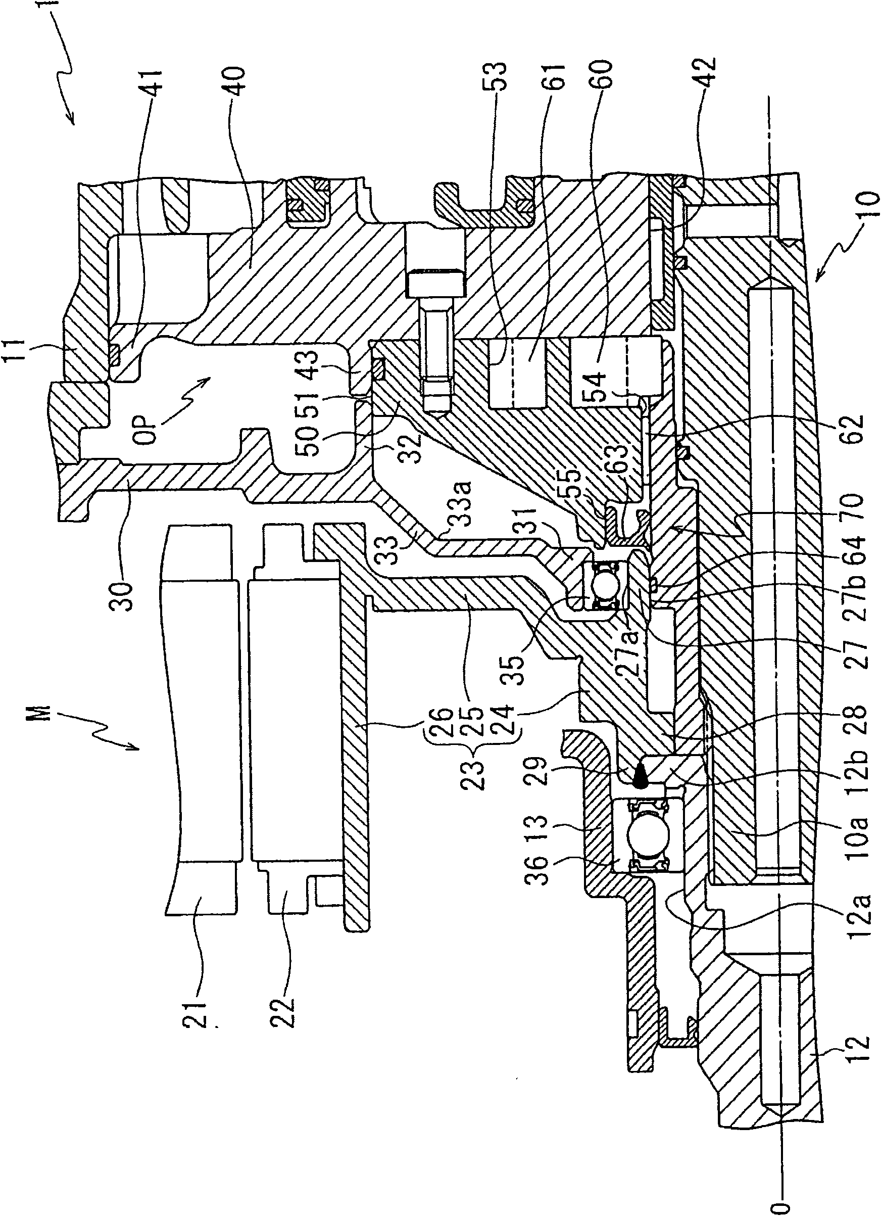
[0035] Next, a case where the support structure of the cylindrical member of the automatic transmission according to the present invention is applied to a cylindrical oil pump drive shaft that transmits rotation of the input shaft to the internal gear of the oil pump will be described as an example.

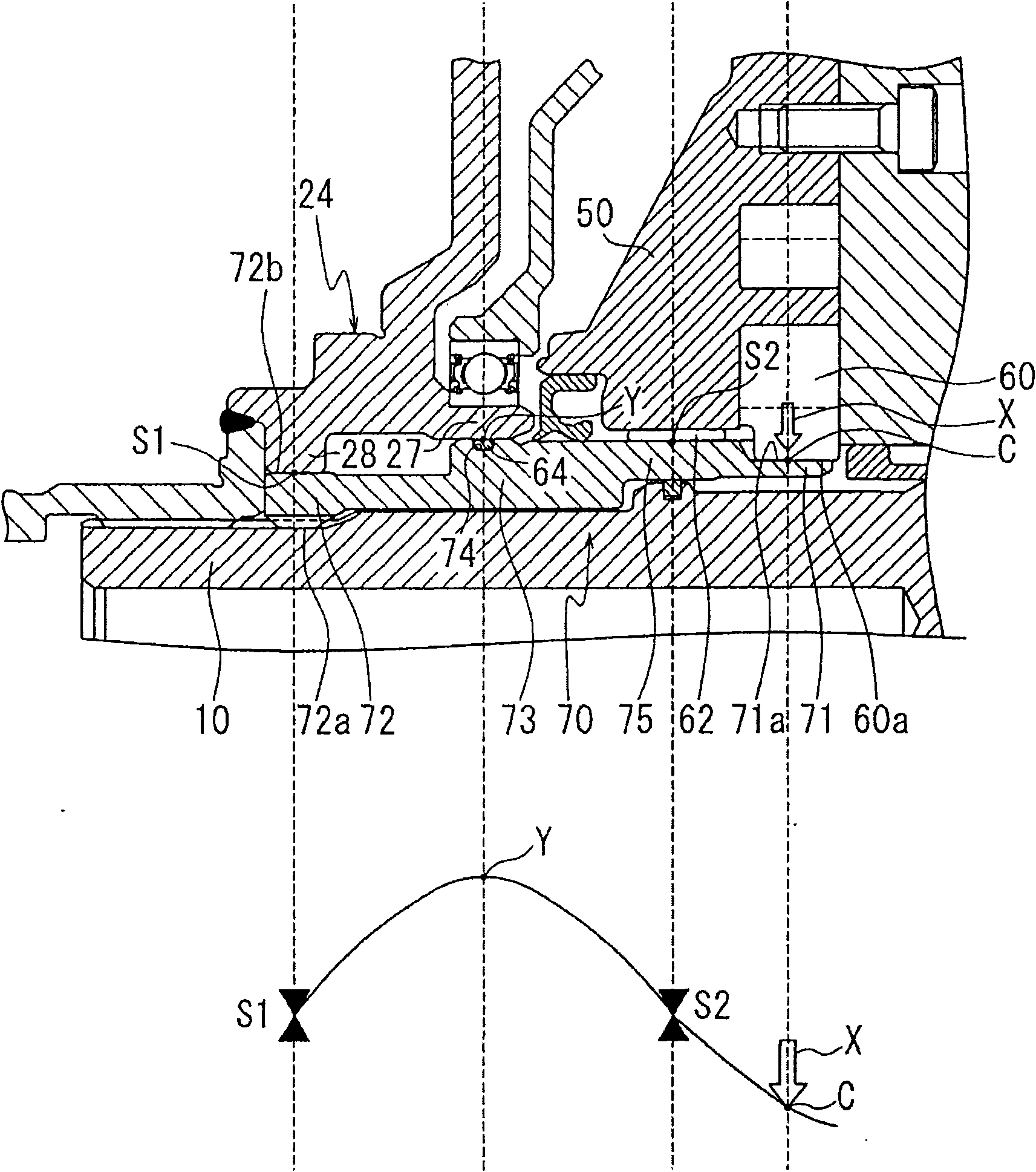
[0036] figure 1 It is a partially enlarged view of an automatic transmission employing the support structure of the embodiment. figure 2 It is a diagram explaining the stress acting on the drive shaft of the oil pump.

[0037] In the automatic transmission 1, along the axial direction of the input shaft 10 of the automatic transmission 1, an electric motor M and an oil pump OP are arranged adjacent to each other in order from the left side in the figure (the engine side not shown), and the oil pump drive shaft 70 is inserted outside the input shaft 10. axis 10.

[0038] The electric motor M is composed of a stator 21 provided on an unillustrated inner peripheral surface of the...


PUM


Abstract

The invention relates to a barrel-shaped part supporting structure for an automatic transmission. The automatic transmission drives an oil pump by transmitting the rotation of an input shaft to an internal gear of oil pump by utilizing the barrel-shaped part of the input shaft. The barrel-shaped part supporting structure can prevent the vibration of the barrel-shaped part from generating noise. Anoil pump driving shaft (70) drives the oil pump by transmitting the rotation of the input shaft (10) of the automatic transmission to an internal gear (60) of oil pump (OP). In the supporting structure of the oil pump driving shaft, the oil pump driving shaft is supported by a shaft sleeve (62) of an oil pump shell (50) and a rotating shaft part (24) of a motor (M). The oil pump driving shaft isformed by setting an O-shaped ring (64) on a position (Y) opposite to an extending part (27) of a rotation shaft outside the oil pump driving shaft, wherein the position (Y) is the position having maximum amplitude when the rotation of the internal gear is transmitted to a connecting part (71) of the oil pump driving shaft.

Description

technical field [0001] The present invention relates to a support structure for a cylindrical member of an automatic transmission. Background technique [0002] In an automatic transmission incorporating an auxiliary motor, the cylindrical member provided on the input shaft has a support structure of a cylindrical member that transmits rotation to an internal gear of an oil pump to drive the oil pump (for example, Patent Document 1). [0003] Patent Document 1: (Japanese) Unexamined Patent Publication Hei 7-76229 [0004] In the device of this conventional example, the rotational vibration accompanying the rotation of the internal gear is directly transmitted to the connecting portion between the cylindrical member and the internal gear of the oil pump, so the cylindrical member may vibrate and become a source of abnormal noise. . Contents of the invention [0005] Therefore, an object of the present invention is to suppress vibration of the cylindrical member without ge...

Claims


Application Information

Patent Timeline
IPC IPC(8): B60K17/06F16H57/00F16F15/04F16F15/08F16H57/02F16H57/023F16H57/028F16H57/029F16H57/03
CPCY02T10/6226F16H57/021F16H57/04
Inventor 大村智洋
Owner JATCO LTD
Why Eureka
Try Eureka