Multi-functional elevator

A lift and multi-functional technology, applied in the field of lifts, can solve the problems of inconvenient use and poor safety of lifts, and achieve the effects of small footprint, easy storage, and compact structural design

Inactive Publication Date: 2010-03-10
王敏奇
1 Cites 47 Cited by

AI-Extracted Technical Summary

Problems solved by technology

[0004] The problem to be solved by the present invention is to provide a simple and compact multi-functional lift for the existing small household ...

Method used

As shown in Figure 3, drive device of the present invention has adopted worm gear reducer, comprises reducer housing 5, and the input stage worm assembly 56 that is connected with electric motor 55 is set at the reducer housing 5 bottom, reducer housing The upper part of the body 5 is provided with an output stage worm gear assembly 50 parallel to the input stage worm assembly 56, and an intermediate stage worm assembly 57 is arranged obliquely between the input stage worm assembly 56 and the output stage worm assembly 50 to transmit power. Assembly 57 includes an intermediate stage worm gear 59 engaged with input stage worm assembly 56 and an intermediate stage worm gear 58 engaged with output stage worm assembly 50 . The obliquely arranged intermediate-stage worm gear assembly 57 solves the disadvantage of the large volume of the two-stage worm transmission, making the internal structure of the worm gear reducer more compact and the transmission efficiency higher. The output stage worm gear assembly 50 includes an output stage worm wheel 52 and a screw shaft 51 linked with the output stage worm wheel 52. The tail of the screw shaft 51 is connected to the cross shaft assembly 54, and the two sides of the output stage worm wheel 52 are re...

Abstract

The invention discloses a multi-functional elevator, comprising a chassis component and a lifting table component, wherein, a scissors mechanism is hinged between the chassis component and the lifting-table component to support or drive the lifting table component; a driving device is arranged on the chassis component to drive the extension and retraction of the scissors mechanism; the driving device is controlled by a controller arranged on the chassis component. The driving device adopts a worm-wheel and worm type speed reducer, and is internally provided with a self-locking mechanism; the chassis component is provided with a roller component with an induction device, and the usage safety of the chassis component is greatly improved. The multi-functional elevator of the invention has small and exquisite appearance structure in design with the thickness being less than one foot under complete compression state, can be completely stored at the bottom of chambers and under beds and other places, occupies less space, and is convenient to be stored. The invention also has multiple functions of being used as an experiment workbench in a laboratory, being used as a table after being lifted to a proper height and being used as a lifting device for placing heavy objects and the like, realizing multiple use of one machine.

Application Domain

Technology Topic

Experimental workSelf locking +7

Image

  • Multi-functional elevator
  • Multi-functional elevator
  • Multi-functional elevator

Examples

  • Experimental program(1)

Example Embodiment

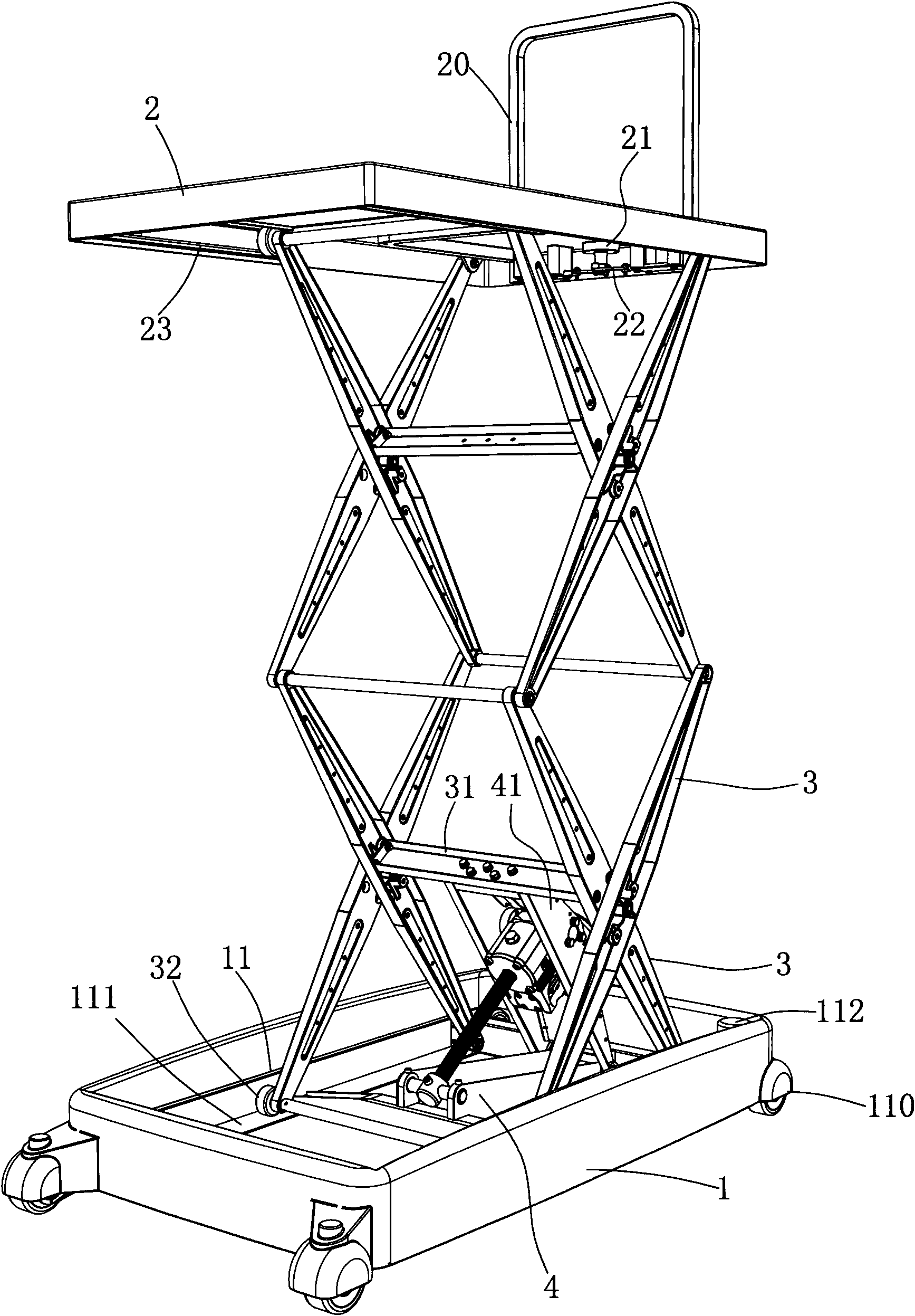
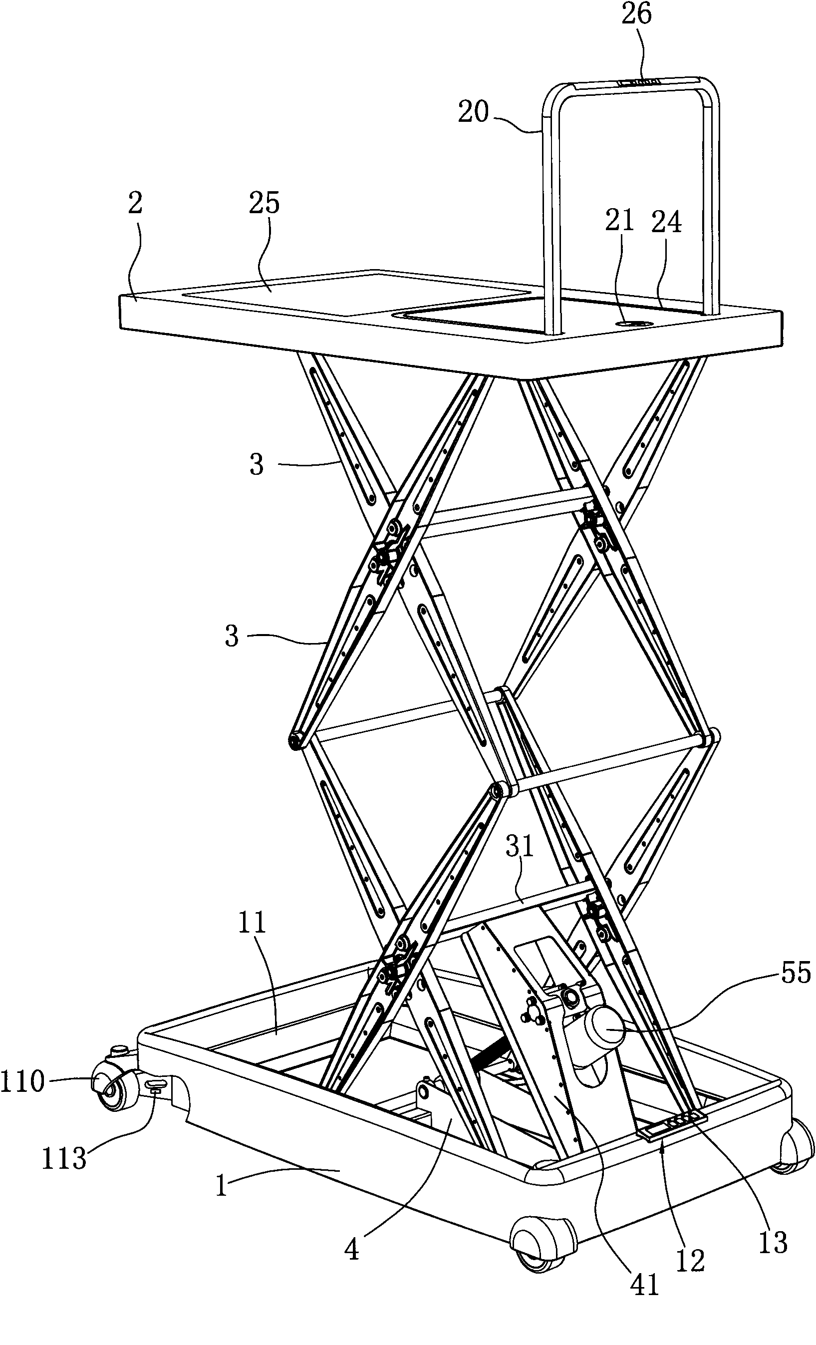
[0020] Such as figure 1 , figure 2 As shown, the present invention is a multifunctional lifter, including a chassis component and a lifting platform component. A scissor mechanism is movably hinged between the chassis component and the lifting platform component to support or drive the lifting platform component. The chassis component is provided with a driving device to drive the scissor fork The expansion and contraction of the mechanism and the driving device are controlled by the controller 12 provided on the chassis assembly.
[0021] The lifting platform assembly includes a lifting platform 2, one end of the lifting platform 2 is movably provided with a folding railing 20, a link mechanism 22 is provided at the bottom of the lifting platform 2 to connect to the bottom of the folding railing 20, and the table surface of the lifting platform 2 is provided with a groove for storing the folding rail 20 24 and the rotating knob 21 of the control link mechanism 22, the folding rail 20 can easily lift heavy objects and be supported by the operator. By operating the rotating knob 21, the folding rail 20 can be locked or moved. The chassis assembly includes a rotomolded housing 1 and a base 11 arranged in the housing 1. Four corners of the base 11 are provided with roller assemblies 110, and the roller assemblies 110 are driven by a mobile driving motor 112 arranged on the base 11. Both the base 11 and the folding railing 20 are provided with operation panels (13, 26) connected to the controller 12, and the mobile driving motor 112 is controlled by the controller 12. A single-chip microcomputer control circuit is provided inside the controller 12, and each roller assembly 110 is provided with a pressure sensor 113 electrically connected to the single-chip control circuit for sensing the pressure of the corresponding roller assembly 110.
[0022] The scissor mechanism between the chassis assembly and the lifting platform assembly is composed of a number of foldable bracket units that are actively hinged. The foldable bracket unit includes two parallel-arranged brackets. The two brackets are connected by a beam 31. The beam 31 at the bottom is also It is fixedly connected with the driving device, and the number of folding bracket units can be increased or decreased according to actual needs. The bracket is formed by cross-hinging two scissor bars 3. The upper and lower ends of one side of the scissor mechanism are hinged with the lifting platform 2 and the chassis 11 through the scissor bars 3, and the upper and lower ends of the scissor mechanism are hinged on the other side of the scissor mechanism. 3 is installed in the rails (23, 111) of the lifting platform 2 and the chassis 11 by rolling wheels 32. The scissor bar 3 can be molded by reinforced SMC, with high strength, stable size and beautiful appearance.
[0023] Such as image 3 As shown, the drive device of the present invention uses a worm gear reducer, including a reducer housing 5, the lower part of the reducer housing 5 is provided with an input stage worm assembly 56 connected to the motor 55, and the upper part of the reducer housing 5 is provided with The input stage worm assembly 56 is parallel to the output stage worm gear assembly 50. An intermediate stage worm gear assembly 57 is arranged obliquely between the input stage worm assembly 56 and the output stage worm gear assembly 50 to transmit power. The intermediate stage worm gear assembly 57 includes an input stage The intermediate worm gear 59 meshed with the worm assembly 56 and the intermediate worm 58 meshed with the output worm gear assembly 50. The obliquely arranged intermediate-stage worm gear assembly 57 solves the disadvantage of the large volume of the double-stage worm drive, and makes the internal structure of the worm gear reducer more compact and higher transmission efficiency. The output-stage worm gear assembly 50 includes an output-stage worm gear 52 and a screw 51 linked to the output-stage worm gear 52. The tail of the screw 51 is connected to a cross shaft assembly 54. Both sides of the output worm gear 52 are provided with thrust bearings 53 for deceleration. The gear housing 5, the cross shaft assembly 54, the toggle plate 41, and the cross beam 31 transfer the driving force to the scissor mechanism. The chassis assembly is provided with a support frame assembly. The worm gear reducer is hinged on the cross shaft assembly 54 through the screw 51 and the cross shaft assembly. On the support frame assembly, the screw drive composed of the screw rod 51 and the output stage worm gear assembly 50 with internal threads has a self-locking function, which can prevent the elevator from falling freely when the power is cut off, and ensure the safety of personnel. The support frame assembly includes a T-shaped support 4 mounted on the chassis assembly. One end of the screw rod 51 is hinged to the front end of the T-shaped support 4, the two ends of the T-shaped support 4 are hinged to the toggle plate 41, and the other end of the toggle plate 41 is fixedly connected. On the cross beam 31 of the scissor mechanism, the cross shaft assembly 54 is hinged with the toggle plates 41 on both sides. The support frame assembly is not only used to install the driving device, but also plays a role in connecting the chassis assembly, the driving device and the scissor mechanism, and improves the support strength of the entire mechanism.
[0024] During use, to control the lift and movement of the elevator, you can select two modes of push and set value on the operation panel. When the set value mode is selected, enter the value and press the corresponding button; when the push mode is selected , Press the corresponding key to control up, down, left, right, let go and stop. Generally speaking, only four buttons of up, down, left and right are provided on the operation panel of the base 11 and the folding railing 20. Press to open, and release to stop. The four buttons are interlocked, and only one button is effective. The present invention uses city power or storage batteries to provide power to the motor, and when both the city power or storage batteries are powered off, the backup battery added on the elevator can be activated, or an emergency cover 25 can be opened on the lifting platform 2. When the emergency cover is opened, the operator can climb down the elevator through the scissor mechanism.
[0025] The above-mentioned specific embodiments are used to explain the present invention, not to limit the present invention. Any modification and change made to the present invention within the spirit of the present invention and the protection scope of the claims should fall into the protection scope of the present invention.

PUM

no PUM

Description & Claims & Application Information

We can also present the details of the Description, Claims and Application information to help users get a comprehensive understanding of the technical details of the patent, such as background art, summary of invention, brief description of drawings, description of embodiments, and other original content. On the other hand, users can also determine the specific scope of protection of the technology through the list of claims; as well as understand the changes in the life cycle of the technology with the presentation of the patent timeline. Login to view more.

Similar technology patents

Axle drive unit for a drive train

InactiveUS20080035405A1Compact designLow transmit torqueDifferential gearingsControl devicesAll-wheel drivePower split
Owner:GKN AUTOMOTIVE LTD BIRMINGHAM +1

Rotating shaft position-limiting device with sensor and position-limiting method thereof

InactiveCN101664856ACompact designQuality changeControl without using feedbackResistance welding apparatusEmbedded systemRotational axis
Owner:深圳翠涛自动化设备股份有限公司

Classification and recommendation of technical efficacy words

  • Compact design
  • Small footprint

Pre-fabricated building modules and method of installation

InactiveUS20050108957A1Low costCompact designSpecial buildingExtraordinary structuresVentilation shaftPrefabrication
Owner:QUESADA JORGE DE
Why Eureka
Try Eureka