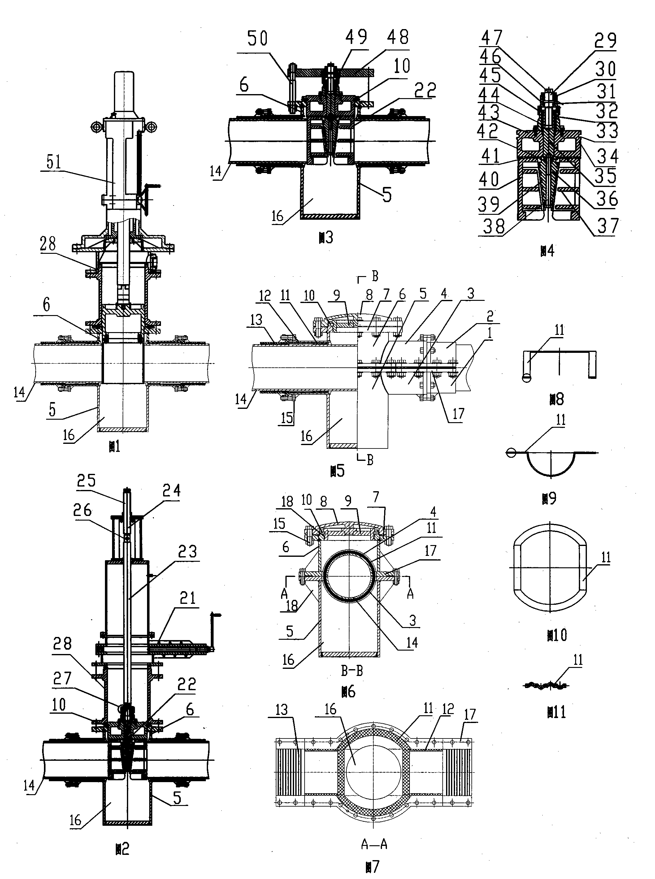
Mechanical pipeline under-pressure blocker and blocking method thereof

A mechanical and blocker technology, applied in the direction of mechanical equipment, pipe components, pipes/pipe joints/pipe fittings, etc., can solve the problems of easy combustion, difficult construction, pollution, etc., to reduce the construction period and construction cost Effect

Active Publication Date: 2010-03-10
济南市公明新技术开发有限公司
View PDF2 Cites 18 Cited by
  • Summary
  • Abstract
  • Description
  • Claims
  • Application Information

AI Technical Summary

Problems solved by technology

However, the hot-pressurized blocking technology for cast iron pipe gas pipelines is still blank in China. However, due to the national conditions, nearly half of the medium and low-pressure gas pipelines in domestic cities and towns are still cast iron pipelines. The transformation, rerouting and replacement of these pipelines adopt traditional methods The completion of the depressurization or gas stop method has brought great difficulty in construction, many unsafe factors, unfavorable to the production and life of gas users, large energy waste and easy to cause a certain degree of pollution. Therefore, technical extension is required on the basis of the original invention. In addition, using patent No. 200720029416.1 to block ordinary steel pipes requires welding construction. If pipeline gas or oil pipelines are used, electric welding construction is easy to cause combustion and explosion accidents

Method used


Image

  • Mechanical pipeline under-pressure blocker and blocking method thereof

Examples


Embodiment

[0046] The conformal sealing pad is made of oil-resistant rubber, which acts as a seal between the upper and lower bodies and the pressure pipeline.

[0047] The supporting rubber pad is made of oil-resistant asbestos rubber sheet, which plays a role in limiting the infinite compression of the conformal sealing rubber pad.

[0048] The inner blind plate is a cylindrical piston, with an annular sealing groove and a limit groove on the side, and a connecting thread protrusion in the center, which is mainly used to seal the dismantled device after the blocking is completed.

[0049] The outer blind plate plays the role of sealing and protection.

[0050] The anti-skid hoop is divided into upper and lower halves. The radius of the inner arc is similar to that of the pipe. There are multiple grooves on the arc, flanges on both sides, and a flat flange on one end to connect the upper and lower bodies.

[0051] How to install and use

[0052] ① After cleaning the curved surface of ...


PUM


Abstract

The invention provides a mechanical pipeline under-pressure blocker and a blocking method thereof. The blocker mainly comprises a process pipe, an under-pressure pipeline mouth gag and an under-pressure pipeline lower blocker, wherein a mechanical encasing-pipe sealing device consists of an upper body, a lower body, a flexible sealing rubber cushion, a sealing support rubber cushion, an upper antiskid anchor ear and a lower antiskid anchor ear; the upper body consists of an upper body pipe and an upper semicircular encasing-pipe plate; the periphery of the upper semicircular encasing-pipe plate is provided with a turned-over edge, and the middle of the upper semicircular encasing-pipe plate is provided with a hole; the lower end of the upper body pipe is welded with the hole, and the upper end of the upper body pipe is welded with a flange; the upper part of the flange is provided with a mouth rim, and a screw hole is horizontally arranged on the mouth rim; the lower body consists of a slag discharge pipe with an opening on the upper end, and a lower semicircular encasing-pipe plate; the periphery of the lower semicircular encasing-pipe plate is provided with a turned-over edge, the middle of the lower semicircular encasing-pipe plate is provided with a hole, and the upper opening of the slag discharge pipe is welded with the hole; and the turned-over edges on the peripheries of the upper semicircular encasing-pipe plate and the lower semicircular encasing-pipe plate are fixed on an under-pressure pipeline by screw bolts. Compared with the prior art, the blocker can block the cast iron pipeline under pressure during operation so as to shorten the construction period and reduce the construction cost.

Description

technical field [0001] The invention relates to a pipeline construction or maintenance technology, in particular to a mechanical pipeline pressure breaker and a blocking method thereof. Background technique [0002] In 2007, the owner of this patent invented "A method and device for blocking pipelines under pressure" (200710113952.4) and "Welded pipeline pressure connector" (200720029416.1), and they were installed in Shanghai, Jinan, Tianjin, Xi'an , Anhui, Weifang and other urban steel pipe gas pipelines have been applied, and the effect is remarkable. However, the hot-pressurized blocking technology for cast iron pipe gas pipelines is still blank in China. However, due to the national conditions, nearly half of the medium and low-pressure gas pipelines in domestic cities and towns are still cast iron pipelines. The decompression or gas stop method is completed, which brings great difficulty in construction, many unsafe factors, unfavorable to the production and life of g...

Claims


Application Information

Patent Timeline
Patent Type & Authority Applications(China)
IPC IPC(8): F16L55/10F16L55/18
Inventor 钊田
Owner 济南市公明新技术开发有限公司
Why Eureka
Try Eureka