Modular LED lamp and manufacture method thereof

A technology for an LED lamp and a manufacturing method, which is applied to lighting devices, cooling/heating devices of lighting devices, light sources, etc., can solve the problems of low heat dissipation efficiency, inability to meet the heat dissipation requirements of LED lamps for high-power urban lighting, and achieve extended use. Longevity, maintaining luminous performance, effect of good luminous performance

Inactive Publication Date: 2010-03-10
DALIAN GOLDEN THERMALWAY TECH
View PDF0 Cites 3 Cited by
  • Summary
  • Abstract
  • Description
  • Claims
  • Application Information

AI Technical Summary

Problems solved by technology

[0011] The purpose of the present invention is to provide a modular LED lamp and its manufacturing method to solve the problems in the prior art that the heat dissipation efficiency is low and cannot meet the heat dissipation requirements of LED lamps for high-power urban lighting

Method used


Image

  • Modular LED lamp and manufacture method thereof
  • Modular LED lamp and manufacture method thereof
  • Modular LED lamp and manufacture method thereof

Examples


Embodiment 1

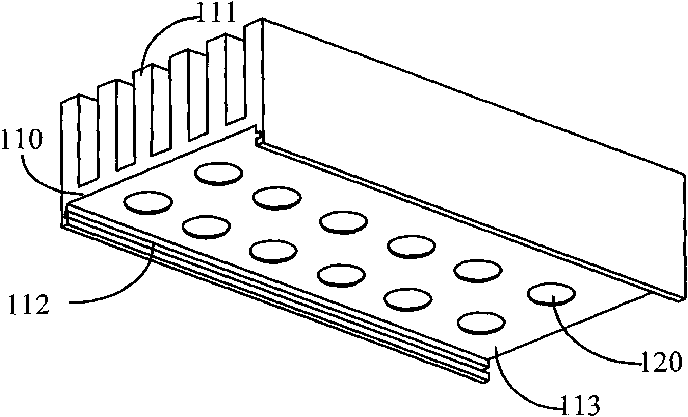
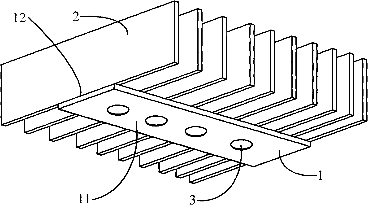
[0044] image 3 A schematic structural diagram of the modular LED lamp provided in Embodiment 1 of the present invention, as shown in image 3 shown. The lamp comprises a strip base 1 and a plurality of cooling fins 2 . The strip-shaped base 1 includes a mounting surface 11 and a heat dissipation surface 12 facing away from each other. The mounting surface 11 is used for mounting LED devices 3, and usually a plurality of LED devices 3 can be installed in a distributed manner; the bottom edges of a plurality of heat dissipation fins 2 are connected to On the heat dissipation surface 12 , and the side of each heat dissipation fin 2 extends beyond the heat dissipation surface 12 of the strip base 1 .

[0045] Such as image 3 As shown, a plurality of heat dissipation fins 2 are preferably parallel to each other, arranged side by side and spaced apart on the heat dissipation surface 12 of the strip base 1 , and each heat dissipation fin 2 is vertically arranged to the heat diss...

Embodiment 2

[0054] Figure 5 The structural schematic diagram of the modular LED lamp provided by Embodiment 2 of the present invention, the difference between this embodiment and Embodiment 1 is that the number of strip bases 1 is at least two, such as Figure 5 Specifically, there may be two strip bases 1 spaced apart from each other, and the heat dissipation fins 2 provided on the heat dissipation surfaces 12 of the plurality of strip bases 1 are connected to each other as a whole.

[0055] In the modular LED lamp of this embodiment, a plurality of strip bases 1 share a set of cooling fins 2 . A certain distance is kept between the strip bases 1 so that air can pass upwards. This structure increases the amount of luminous light without increasing the overall heat dissipation burden of the lamp. In this way, LED lamps with high power and high luminous flux can be made. Obviously, the number of strip bases 1 can continue to increase according to design requirements.

Embodiment 3

[0057] Figure 6 It is a schematic structural diagram of a modular LED lamp provided by Embodiment 3 of the present invention. This embodiment can be based on the first embodiment, and this embodiment further adds a side baffle 4 , and a side baffle 4 is connected to the sides of a plurality of cooling fins 2 . Such as Figure 6 As shown, two side baffles 4 are respectively connected to the two sides of a plurality of parallel cooling fins 2 , and the side baffles 4 are used to seal the cooling fins 2 into a cylindrical structure.

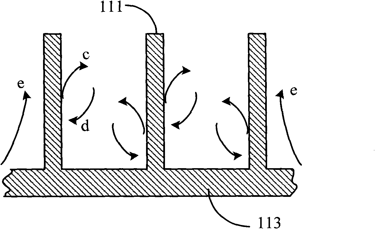
[0058] The advantage of the modular LED lamp structure provided in this embodiment is that it can reduce the influence of lateral interfering airflow, so that the cooling air can pass through the gaps between the cooling fins 2 smoothly from bottom to top. In addition, during the heat dissipation work, negative pressure appears in the gap between the heat dissipation fins 2 due to the upward movement of the air. After the external cold air is blo...


PUM


Abstract

The invention provides a modular LED lamp and a manufacture method thereof. The lamp comprises a strip-shaped base, a plurality of radiating fins and LED components, wherein the strip-shaped base comprises an installing surface and a radiating surface which are back to each other, the LED components are distributed and arranged on the installing surface; bottom edges of the radiating fins are connected to the radiating surface, wherein the width of each radiating fin is larger than that of the radiating surface, and two sides of the radiating fins extend to exceed the margin of the radiating surface. The technical scheme of the embodiment of the invention can ensure that heat produced by the LED components can smoothly and successfully radiated by the radiating fins so as to further prolong the service life of the LED components and keep better luminescence performance.

Description

technical field [0001] Embodiments of the present invention relate to lighting lamp technology, and in particular to a modular light emitting diode (Light Emitting Diode; hereinafter referred to as: LED) lamp and a manufacturing method thereof. Background technique [0002] The advent of the semiconductor lighting device-LED light source has made the traditional lighting technology take another leap forward. Due to its energy-saving, environmental protection and long-lasting characteristics, LED light sources are gradually replacing traditional lighting sources represented by incandescent lamps. This trend has spread rapidly around the world. [0003] However, due to the constraints of material properties and manufacturing technology, the currently widely used LED light sources (or LED devices) still have some unsatisfactory defects, mainly manifested in low electro-optical conversion efficiency. According to theoretical calculations, an LED device should have an effective ...

Claims


Application Information

Patent Timeline
IPC IPC(8): F21S2/00F21V29/00F21V19/00F21Y101/02F21K9/20F21V29/76F21Y115/10
Inventor 杨洪武车廷建
Owner DALIAN GOLDEN THERMALWAY TECH
Why Eureka
Try Eureka