Combined heat pipe exchanger

A heat pipe heat exchanger, heat pipe technology, applied in the direction of heat exchanger shell, indirect heat exchanger, heat exchange equipment, etc., can solve problems such as poor thermal conductivity, reduce energy loss, improve transmission efficiency, and save costs.

Active Publication Date: 2010-03-10
合肥万豪能源设备有限责任公司
View PDF1 Cites 23 Cited by
  • Summary
  • Abstract
  • Description
  • Claims
  • Application Information

AI Technical Summary

Problems solved by technology

The heat exchanger integrates the high thermal conductivity of the heat pipe, which overcomes the shortcomings of poor thermal conductivity of common heat exchanger materials in the industry

Method used


Image

  • Combined heat pipe exchanger
  • Combined heat pipe exchanger
  • Combined heat pipe exchanger

Examples


Embodiment Construction

[0016] The following is a detailed description of the embodiments of the present invention. This embodiment is implemented on the premise of the technical solution of the present invention, and detailed implementation methods and specific operating procedures are provided, but the protection scope of the present invention is not limited to the following implementation example.

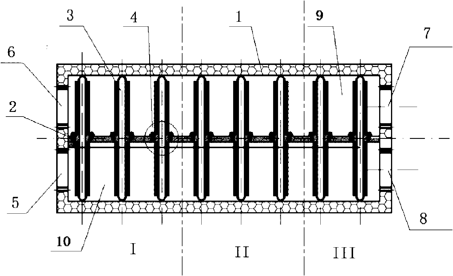
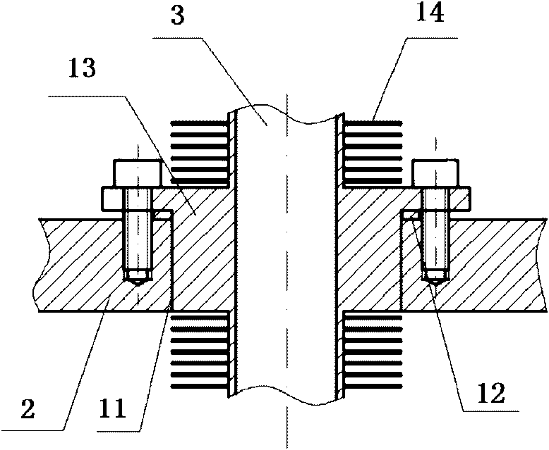
[0017] Such as figure 1 As shown, this embodiment includes: a box body 1, a partition plate 2, several heat pipes 3 and a heat pipe fixing structure 4, wherein: the two ends of the box body 1 are respectively provided with a natural gas inlet pipeline 5, a refrigerant outlet pipeline 6 and Refrigerant inlet pipeline 7, liquefied natural gas outlet pipeline 8, one end of the partition 2 is fixedly arranged between the natural gas inlet pipeline 5 and the refrigerant outlet pipeline 6 at one end inside the box body 1, and the other end of the partition 2 is fixed Set between the refrigerant inlet pipeli...


PUM


Abstract

The invention relates to a combined heat pipe exchanger in the technical field of refrigeration, which comprises a box body, a clapboard, a plurality of heat pipes and a heat pipe fixing structure, wherein two ends of the box body are respectively and correspondingly provided with a natural gas inlet pipeline, a refrigerant outlet pipeline, a refrigerant inlet pipeline and a liquefied natural gasoutlet pipeline; one end of the clapboard is fixedly arranged between the natural gas inlet pipeline and the refrigerant outlet pipeline which are at one end in the box body; the other end of the clapboard is fixedly arranged between the refrigerant inlet pipeline and the liquefied natural gas outlet pipeline which are at the other end in the box body; the heat pipe fixing structure is fixedly arranged on the clapboard; and the heat pipes are connected with the heat pipe fixing structure and vertical to the clapboard. The combined heat pipe exchanger integrates the characteristic of high-thermal conductivity of the heat pipes and overcomes the defect of poor heat-conducting property of the common heat exchanger material in the current industry.

Description

technical field [0001] The invention relates to a device in the technical field of refrigeration, in particular to a combined heat pipe heat exchanger suitable for a natural gas liquefaction process. Background technique [0002] At present, liquefied natural gas (LNG) technology has become a new industry and is developing rapidly. During the liquefaction process, the heat exchange efficiency between natural gas and refrigerant is one of the key factors determining the liquefaction rate and energy consumption of natural gas, and is also directly related to the output rate and economy of LNG. At present, in the natural gas liquefaction process widely used in the industry, plate-fin heat exchangers and shell-and-tube heat exchangers are mainly used. Restricted by the thermal conductivity of aluminum, copper, etc., the heat transfer efficiency is low, so the volume is very large. In view of the fact that there are a large number of marginal gas fields with small gas productio...

Claims


Application Information

Patent Timeline
Patent Type & Authority Applications(China)
IPC IPC(8): F28D15/02F28F9/00F28F9/26F28F1/24
CPCF28D15/0275
Inventor 巨永林王刚
Owner 合肥万豪能源设备有限责任公司
Why Eureka
Try Eureka