Non-360-degree targeting navigation method for detecting robot
A navigation method and robot positioning technology, applied in the field of automatic control, can solve the problems of high precision of mechanical devices, not economically feasible, and inapplicable
- Summary
- Abstract
- Description
- Claims
- Application Information
AI Technical Summary
Problems solved by technology
Method used
Image
Examples
Embodiment 1
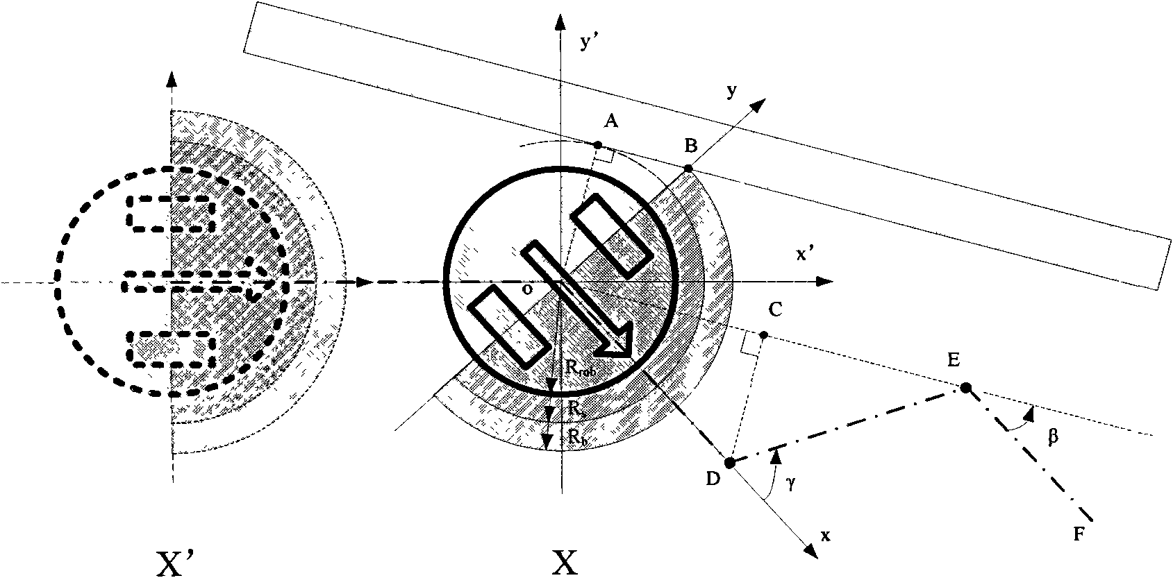
[0084] figure 2 is a schematic diagram of the robot circumventing the edge of an obstacle whose contour is a straight line. The robot advances in a straight line from position X' towards the target, and encounters an obstacle at point O (by the virtual antennae Dsc s Detected) stops and starts to avoid steering until the virtual antenna Dscb detects no obstacles, and the turning angle is β, where β is the angle that the robot turns from when the avoiding steering action ends to when the avoiding steering action ends. Then start walking in a straight line. During the straight-line walking process, the antenna Barl or Barr detects the stroke d until d is greater than a certain value of Rb, which is the position D in the figure. Then it starts to approach the steering, and the turning angle γ is taken as a fixed value. In this design, γ=2β, so that after the TURN-IN at point D ends, it will walk straight to E (repeat the above-mentioned action at point O at this time), and the l...
Embodiment 2
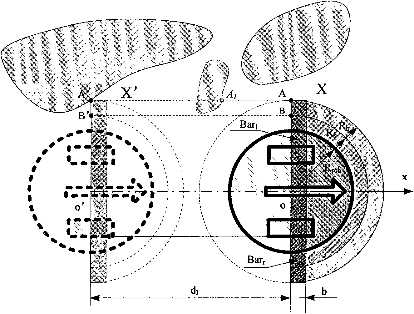
[0086] image 3 It is a schematic diagram of a robot walking in a pure straight line around the edge of a complex obstacle. When the robot walks in a straight line in the mode of circumventing the obstacle edge, the rectangular tentacles of Bar l with Bar r Record the distance d(d l with d r ), when the value of d is greater than R b At this time, it ends by walking in a straight line. In order to ensure the stability of the action in the case of random obstacles, whenever the rectangular antennae Bar l with Bar r When an obstacle is detected, the d value is reset to zero. In other words, d represents the barrier-free walking distance in pure straight line mode, when it is greater than a certain value (D th ) when the pure straight line walking mode ends. image 3 The robot d is cleared at position X’, if the obstacle A 1 exists, then d is leaving A 1 This can effectively ensure that the robot will not be too close to the obstacle when the pure straight line walking...
Embodiment 3
[0088] Figure 4 It is a schematic diagram of the trajectory of the robot around the edge of the thin plate (obstacle). The obstacle is a thin plate, and the robot is required to turn 180° as quickly as possible to get around the edge of the obstacle. The barrier-free walking distance threshold D in the straight-line walking mode in the figure th take as R b , that is, walking in a straight line on the semi-circular antennae Dsc b It ends at the point of intersection with the x-axis (point A in the figure). The orbiting trajectory of the robot determined in this embodiment is the dotted line OABCDEFGHIJK. From the figure it is easy to see whether each turn is an approach turn or a target turn or an avoidance turn. Every time the turning angle is γ, it must turn at least 180 / γ times in the range of 180°, and there may be TURN-OUT in the actual detour process, so the number of pure turns is higher than 180 / γ times.
PUM
 Abstract
Description
Claims
Application Information
 - R&D
- Intellectual Property
- Life Sciences
- Materials
- Tech Scout
- Unparalleled Data Quality
- Higher Quality Content
- 60% Fewer Hallucinations
Browse by: Latest US Patents, China's latest patents, Technical Efficacy Thesaurus, Application Domain, Technology Topic, Popular Technical Reports.
© 2025 PatSnap. All rights reserved.Legal|Privacy policy|Modern Slavery Act Transparency Statement|Sitemap|About US| Contact US: help@patsnap.com


