Power supply providing ultrafast modulation of output voltage

A circuit and current technology, applied in the direction of output power conversion device, conversion of DC power input to DC power output, amplifier with semiconductor device/discharge tube, etc., can solve problems such as inappropriate

Inactive Publication Date: 2010-03-10
ASTEC INT LTD
View PDF0 Cites 58 Cited by
  • Summary
  • Abstract
  • Description
  • Claims
  • Application Information

AI Technical Summary

Problems solved by technology

This makes conventional pwm dc-dc converters unsuitable as power supplies for devices such as rf power amplifiers that require ultrafast modulation of their supply voltage

Method used


Image

  • Power supply providing ultrafast modulation of output voltage
  • Power supply providing ultrafast modulation of output voltage
  • Power supply providing ultrafast modulation of output voltage

Examples


Embodiment Construction

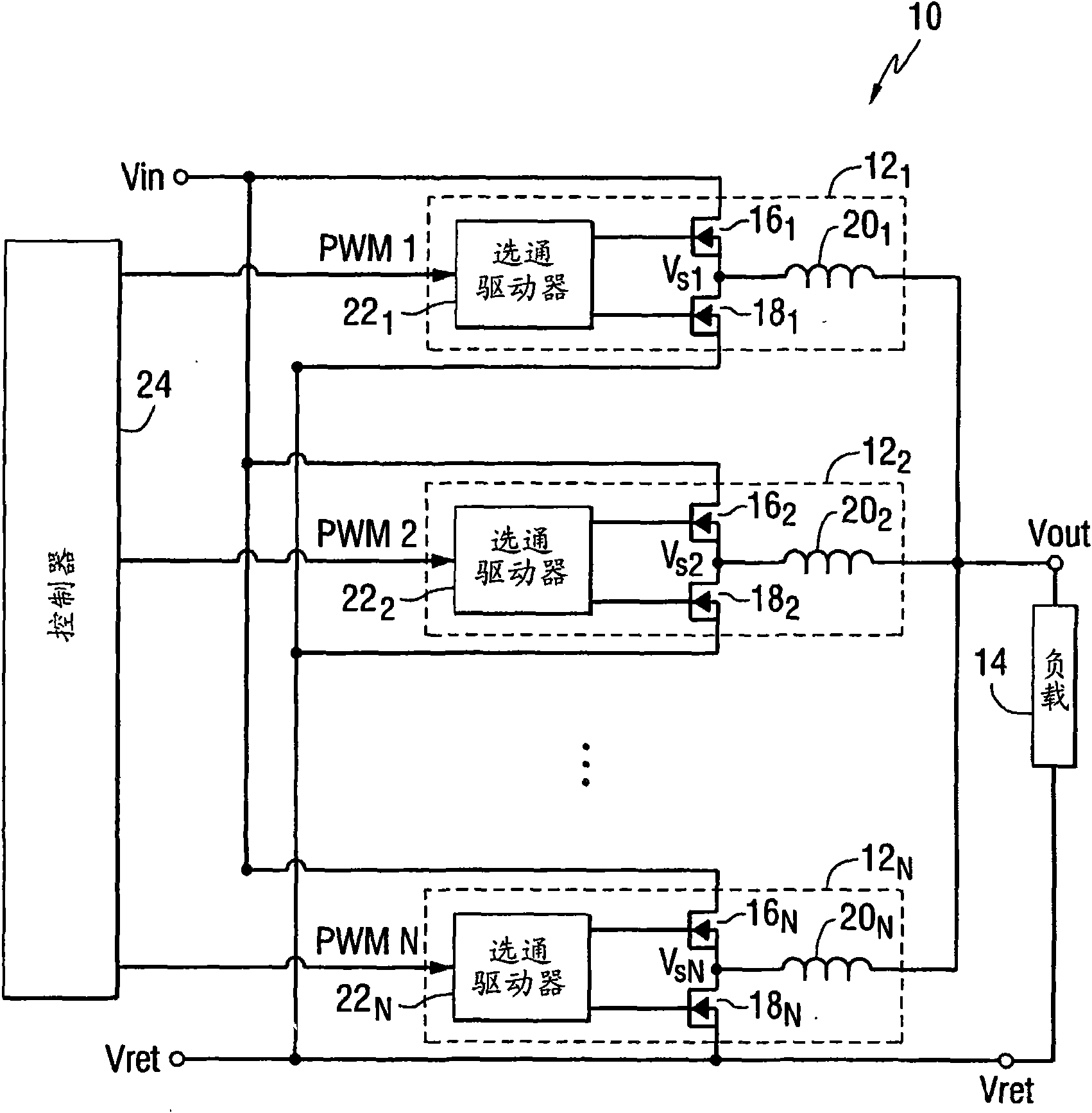
[0024] figure 1 is a schematic diagram of a power supply 10 according to various embodiments of the invention. The power supply 10 includes a certain number (N) of parallel-connected switching mode power modules 12 1-N . 12 per power module 1-N can both convert a common input voltage (Vin) to a corresponding output voltage of the same average magnitude, which allows the module 12 1-N Such as figure 1 are shown connected together to power a load 14 .

[0025] 12 per power module 1-N They may be identical in structure, but operate in a phase shifted (or "interleaved") relative to each other as explained in more detail below. Such as figure 1 As shown, according to one embodiment, each power module 12 1-N may include, for example, a synchronous buck converter. In this connection, the power module 12 1-N may include power switches 16 1-N , synchronous rectifier 18 1-N , output inductor 20 1-N and 16 for the power switch 1-N and synchronous rectifier 18 1-N Gate d...


PUM


Abstract

A circuit for use with a power amplifier that amplifies an input signal. The circuit may comprise an amplitude correction circuit and an open-loop switching regulator. The amplitude correction circuit may be configured to generate a corrected envelope signal from an input envelope signal that represents an envelope of the input signal. The open-loop switching regulator may be connected to the amplitude correction circuit and may be for powering the power amplifier based on the corrected envelope signal. According to various embodiments, the corrected envelope signal generated by the amplitudecorrection circuit is a function of the input envelope signal and an error voltage of the open-loop switching regulator.

Description

[0001] priority claim [0002] This application claims priority to US Provisional Application Serial No. 60 / 894,570, filed March 13, 2007, which is incorporated herein by reference. technical field [0003] The present invention generally relates to power conversion circuits. Background technique [0004] Many different electronic devices require very fast modulation of their supply voltage. One such type of electronic device is a radio frequency (rf) linear power amplifier. Such amplifiers are widely used in modern wireless communication devices and infrastructure. In complex modulation schemes used in wireless communications like QPSK, CDMA, WCDMA, the amplitude of the envelope of the rf signal varies significantly. Whenever the envelope of the rf signal falls sufficiently below the maximum value allowed by the supply voltage, the efficiency of the power amplifier is severely degraded. In other words, a large part of the supplied energy is only used to maintain the ope...

Claims


Application Information

Patent Timeline
Patent Type & Authority Applications(China)
IPC IPC(8): H03F1/02H03F1/32H02M3/158H03F3/19
CPCH03F2200/432H03F3/19H03F1/3247H03F2201/3233H03F3/217H02M2001/0045H03F1/0227H03F2200/102H02M1/0045
Inventor 皮奥特·马科斯基王林国
Owner ASTEC INT LTD
Why Eureka
Try Eureka