Stop valve of pipeline

A technology for stop valves and pipelines, which is applied in the direction of lifting valves, valve devices, engine components, etc., can solve the problems of inability to reduce the local flow resistance of the valve chamber, vortex generation, and complicated medium flow, so as to save pipeline operating costs and reduce fluid flow. Effect of drag, local drag drop

Inactive Publication Date: 2010-03-17
GUANGDONG LIANSU TECH INDAL
View PDF0 Cites 7 Cited by
  • Summary
  • Abstract
  • Description
  • Claims
  • Application Information

AI Technical Summary

Problems solved by technology

This structure can effectively reduce the pressure of the stagnant fluid on the valve stem, but it makes the medium flow more complicated and cannot reduce the local resistance of the flow in the valve cavity.
In addition, when the medium flows through the existing globe valve, due to the medium delivery pressure, the medium directly impacts on the valve disc, and a vortex is generated in the valve body, causing a large energy loss to the entire pipeline system
The above-mentioned energy loss has accounted for 80% of the power to maintain pipeline operation in the existing pipeline system, which is a major defect of the existing globe valve

Method used


Image

  • Stop valve of pipeline
  • Stop valve of pipeline
  • Stop valve of pipeline

Examples


Embodiment Construction

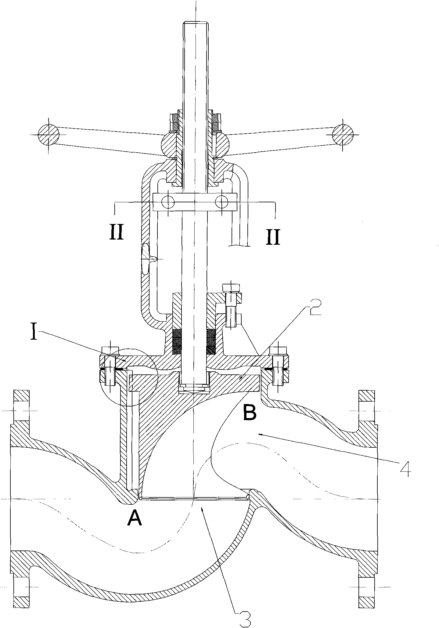
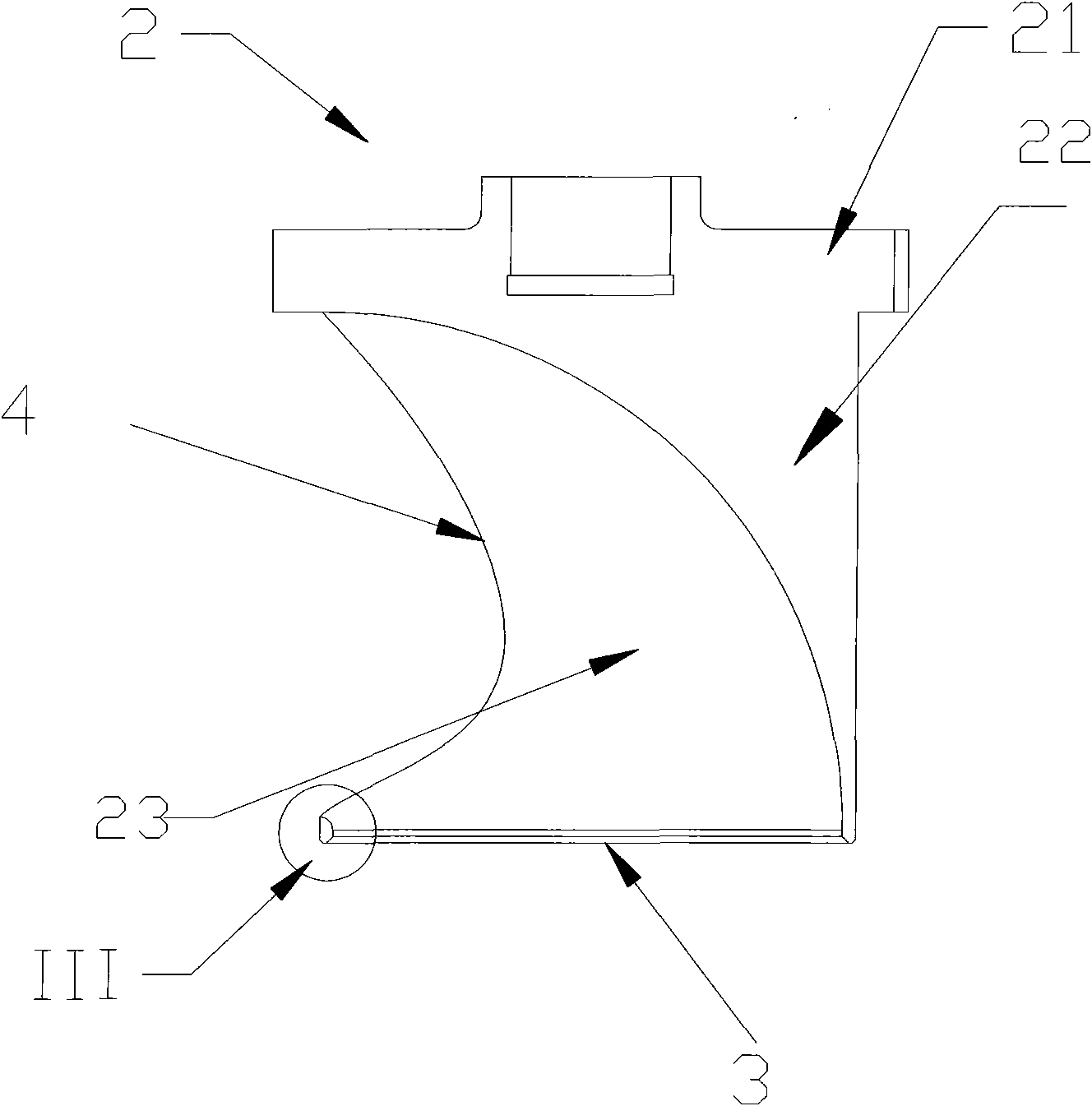
[0017] Such as figure 1 , figure 2 As shown, the present invention includes a valve body 1 and a valve disc 2, the fluid inlet 3 and the fluid outlet 4 of the valve body 1 turn smoothly at 90 degrees, and the outer surface of the valve disc 2 is formed by an integral flat-shaped sealing disc 21 and a lower cylinder 22 perpendicular to the sealing valve plate 21, the inner surface of the lower cylinder 22 of the valve disc is a cylindrical ring surface 23, and the cylindrical ring surface 23 is at the fluid inlet 3 and the sealing surface of the valve seat 5 is vertical, and the outlet 4 is tangent to the valve body inlet 6, that is, the tangent to the centerline of the cylinder annulus at the outlet 4 coincides with the tangent to the centerline of the cross-section at the valve body inlet. Said cylindrical ring surface 23 can be a cylindrical ring with equal diameter, or a cylindrical ring with variable diameter.

[0018] When the valve is fully open, the outer cylindrical...


PUM


Abstract

The invention discloses a stop valve of a pipeline, which comprises a valve clack, wherein the valve clack comprises a sealed valve plate and a lower cylindrical body which is vertical to the valve plate; the internal surface of the lower cylindrical body of the valve clack is a cylindrical ring surface, the cylindrical ring surface is vertical to the sealed surface of a valve seat at a fluid inlet, and an outlet is tangential to an inlet of a valve body, i.e. the tangential line of the center line of the cylindrical ring surface at the outlet is superposed with the tangential line of the center line of the section at the inlet of the valve body. The cylindrical ring surface can be a cylindrical ring with equal diameter and can be also a cylindrical ring with variable diameter. The valve clack of the stop valve structure can lower the local resistance of the valve obviously, lower the pressure of a medium on a valve rod because the structure of the valve clack enables the medium to smoothly flow from an inlet of a valve cavity to an outlet, reduce the energy loss of the pipeline valve greatly, save the running cost of the pipeline and play an indispensable positive role in the aspects of environmental protection and energy saving.

Description

technical field [0001] The invention belongs to the technical field of pipeline valves, in particular to a pipeline stop valve. Background technique [0002] In the existing pipeline stop valve structure, the fluid medium inlet is designed to be perpendicular to the bottom surface of the valve disc, and the medium flows into the valve cavity from the inlet in a direction perpendicular to the bottom surface of the valve disc and directly impacts on the bottom surface of the valve disc in a direction perpendicular to the bottom surface of the valve disc. , and then turn at a right angle and enter the outlet of the valve cavity. The local resistance loss caused by this flow mode is relatively large, which is about three times that of the same medium turning smoothly through 90° under the same pressure and flow velocity. And because the high-pressure fluid directly impacts on the bottom surface of the disc in the vertical direction, after the fluid touches the bottom surface, p...

Claims


Application Information

Patent Timeline
IPC IPC(8): F16K1/06F16K1/36F16K1/50
Inventor 黄虹宾
Owner GUANGDONG LIANSU TECH INDAL
Why Eureka
Try Eureka