Erecting method of underground roadway filling pipeline

A pipeline hanger and pipeline technology, which is applied in the direction of filling, mining equipment, earthwork drilling, etc., can solve the problems of easy sedimentation of slurry, increase of local resistance, and increase of roadway section, so as to reduce labor intensity of workers and local Resistance, avoiding the effect of bumps and ups and downs

Pending Publication Date: 2021-02-02
MCC NORTH (DALIAN) ENG TECH CO LTD
View PDF8 Cites 3 Cited by
  • Summary
  • Abstract
  • Description
  • Claims
  • Application Information

AI Technical Summary

Problems solved by technology

[0002] At present, underground filling pipelines in mines are mostly laid along the roadway floor or erected along the side wall of the roadway. When the pipeline satisfies the safe passage of vehicles and personnel, the width of the roadway is relatively large, and the arch height is proportional to the width of the roadway. Therefore, it will inevitably lead to a larger section of the roadway, which will increase the amount of roadway excavation and support works, especially when the filling pipeline is erected along the side wall of the roadway. Both conflict with the position of the filling pipeline, so the filling pipeline needs to be erected on the side wall of the roadway on the opposite side of the pressure air and water supply pipes, resulting in further enlargement of the roadway section
At the same time, along the roadway along the vein that the main horizontal main filling pipeline passes through, it needs to cross many chambers connecting roadways or branch roadways, so the filling pipeline needs to cross the door frequently. , the slurry in the pipeline between the two convex cross-doors is easy to deposit; on the contrary, when the lower-span door is used, the filling pipe becomes concave, which also greatly increases the local resistance, and the slurry in the pipeline at the concave cross-door is easy to deposit , and the pipeline at the concave cross door has the risk of being damaged by vehicles and people
In addition, when the filling pipeline is laid along the roadway floor, it is not easy to detect the leakage of the pipeline during the inspection

Method used


Image

  • Erecting method of underground roadway filling pipeline
  • Erecting method of underground roadway filling pipeline
  • Erecting method of underground roadway filling pipeline

Examples


Embodiment Construction

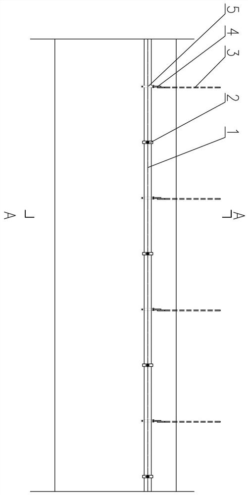
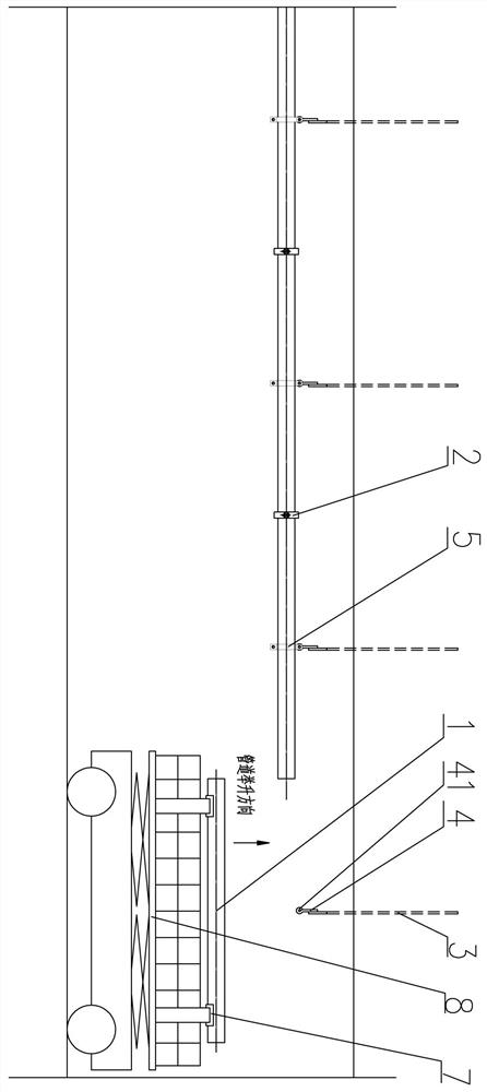
[0029] Such as Figure 1-Figure 7 As shown, the erection method of a kind of downhole filling pipeline of the present invention is characterized in that: comprises the following steps:

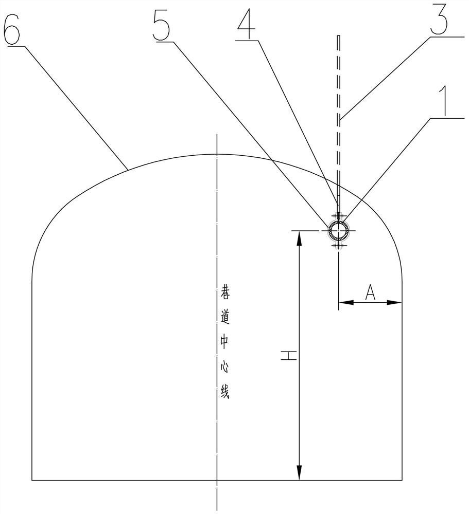
[0030] Step 1: Determine the height of the filling pipeline from the floor of the roadway 6 according to the safe passage height of vehicles and equipment,

[0031] The determination of the safe passage height of its vehicles and equipment refers to the safe passage height of the equipment. The gap between the protruding parts is ≥300mm.

[0032] Step 2: Arrange the anchor rods 3 in a row at equal intervals along the flow direction of the slurry in the filling pipeline 1 on the vault of the tunnel 6; The bottom of the bottom is welded with a tail ring 41, and the upper end of the anchor rod 3 is fixed on the vault of the roadway 6 through a cement mortar anchor;

[0033] Step 3: Layout of the filling pipeline

[0034] The filling pipeline 1 is composed of multiple pipe sections, and each s...


PUM


Abstract

The invention relates to an erecting method of an underground roadway filling pipeline. The erecting method is characterized by comprising the following steps that (1) the height from a filling pipeline to a bottom plate of a roadway is determined; (2) a row of anchor rods are preset on a vault of the roadway at equal intervals in the flowing direction of slurry in the filling pipeline, a pipelinehanging bracket pull rod is arranged at the lower ends of the anchor rods in a welded mode, a tail ring is arranged at the lower part of the pipeline hanging bracket pull rod in a welded mode, and the upper ends of the anchor rods are anchored on the vault of the roadway through cement mortar; and (3) the filling pipeline is composed of a plurality of pipe sections, each section of filling pipeline is connected with an upstream filling pipeline by adopting a clamp type connector, pipe clamping clamps are arranged in the middle of each section of filling pipeline, and the pipe clamping clampsare fixedly connected with the tail ring of the hanging bracket pull rod through a bolt, a gasket and a nut until the tail end of the filling pipeline in a filling stope is reached. The erecting method of the underground roadway filling pipeline has the advantages that the pipeline is convenient to mount and dismount, the width and the sectional area of a roadway can be reduced, the engineering quantity is saved, and the local resistance of filling slurry conveying can be further reduced.

Description

technical field [0001] The invention relates to a mine mining and filling system, in particular to a method for erecting an underground roadway filling pipeline auxiliary for mine filling. Pipeline transportation of filling slurry. Background technique [0002] At present, underground filling pipelines in mines are mostly laid along the roadway floor or erected along the side wall of the roadway. When the pipeline satisfies the safe passage of vehicles and personnel, the width of the roadway is relatively large, and the arch height is proportional to the width of the roadway. Therefore, it will inevitably lead to a larger section of the roadway, which will increase the amount of roadway excavation and support works, especially when the filling pipeline is erected along the side wall of the roadway. Both conflict with the position of the filling pipeline, so the filling pipeline needs to be erected on the side wall of the roadway on the opposite side of the pressure air and ...

Claims


Application Information

Patent Timeline
Patent Type & Authority Applications(China)
IPC IPC(8): E21F17/02E21F15/08
CPCE21F17/02E21F15/08
Inventor 孙冠男巴家泓周育刘召胜
Owner MCC NORTH (DALIAN) ENG TECH CO LTD
Why Eureka
Try Eureka