
Refrigerant system oil accumulation removal

A refrigerant and refrigerant circuit technology, which is applied in refrigerators, refrigeration components, refrigeration and liquefaction, etc., can solve problems such as system performance degradation, evaporator efficiency reduction, and HVAC system cost increase, to avoid wear problems and reduce costs. Effect

Active Publication Date: 2010-03-17
GM GLOBAL TECH OPERATIONS LLC
View PDF0 Cites 2 Cited by
  • Summary
  • Abstract
  • Description
  • Claims
  • Application Information

AI Technical Summary

Problems solved by technology

However, system performance may be reduced as additional oil in the evaporator may reduce evaporator efficiency
Also, the extra oil in the system will increase the cost of the HVAC system

Method used


Image

  • Refrigerant system oil accumulation removal
  • Refrigerant system oil accumulation removal
  • Refrigerant system oil accumulation removal

Examples


Embodiment Construction

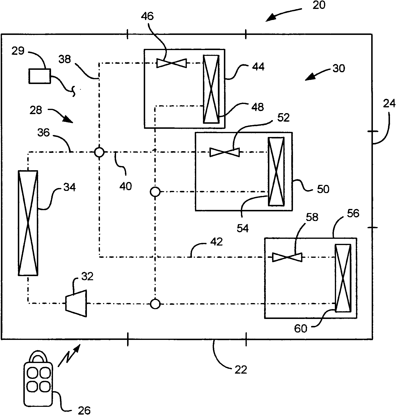
[0016] refer to figure 1 , a vehicle generally indicated at 20 is shown. The vehicle 20 includes doors 22 and may include a hatch 24 or a key fob 26 (or other keyless entry system). Vehicle 20 also includes a heating, ventilation and air conditioning (HVAC) system 28 controlled by controller 29 .

[0017] The HVAC system 28 includes a refrigerant system 30 having a compressor 32, a condenser 34, and a plurality of refrigerant circuits connected by refrigerant lines 36 that direct refrigerant through the various components. The refrigerant contains oil, which flows with the refrigerant to provide lubrication to the compressor 32 . figure 1 The exemplary embodiment shown includes three refrigerant circuits: a front refrigerant circuit 38 , a rear (also referred to as auxiliary) refrigerant circuit 40 , and a battery refrigerant circuit 42 . The front refrigerant circuit includes a front HVAC module 44 having a front expansion device 46 and a front evaporator 48 . The post re...


PUM


Abstract

The invention relates to refrigerant system oil accumulation removal, and discloses a method and a system for removing oil accumulation from refrigerant lines of a vehicle HVAC system having multiplerefrigerant loops each having an evaporator is disclosed. The method for operating the system may comprise the steps of: monitoring a flow rate through at least one of the refrigerant loops; determining if the flow rate through any of the at least one refrigerant loops being monitored is below a predetermined flow rate for greater than a predetermined time limit; monitoring for an indication of imminent vehicle operation; and if the indication of imminent vehicle operation is detected and the flow rate through any of the at least one refrigerant loops being monitored is below the predeterminedflow rate for greater than the predetermined time limit, opening a valve to allow for maximum flow through the at least one refrigerant loop.

Description

technical field [0001] The present invention generally relates to vehicle heating, ventilation and air conditioning (HVAC) systems having multiple evaporators. Background technique [0002] Vehicle HVAC systems may have multiple evaporators. For example, a vehicle may have a front HVAC module, a rear HVAC module, and a battery pack cooling module, each with a refrigerant circuit directing refrigerant (including oil) through its respective evaporator. Such HVAC systems have different refrigerant flow rates in each circuit depending on the specific cooling needs of that circuit at any given moment. That is, if there are no passengers in the rear of the cabin, sometimes the cooling demand of the front HVAC module is high and the demand of the rear HVAC module is low (or none). Furthermore, under some vehicle operating conditions, the battery pack cooling load may be significantly less than the passenger cabin cooling load, while under other operating conditions, there may be ...

Claims


Application Information

Patent Timeline
Patent Type & Authority Applications(China)
IPC IPC(8): F25B49/02F25B41/04F25B41/06F25B31/00B60H1/32
CPCF25B31/004F25B5/02B60H1/323F25B2500/16
Inventor L·P·齐尔G·A·梅杰
Owner GM GLOBAL TECH OPERATIONS LLC
Learn More