
Stereoscopic acquisition equipment for obtaining optical properties of object

A technology of optical properties and acquisition equipment, applied in optics, stereo photography, instruments, etc., can solve problems such as lack of flexibility, and achieve the effect of convenient disassembly and adjustment

Inactive Publication Date: 2010-03-17
BEIHANG UNIV
View PDF0 Cites 3 Cited by
  • Summary
  • Abstract
  • Description
  • Claims
  • Application Information

AI Technical Summary

Problems solved by technology

Literature [6] built an acquisition device similar to this article, but the device only completes half of the entire 2V Geodesic Dome sphere, and the positions of the camera and light source are fixed, so the flexibility is insufficient

Method used


Image

  • Stereoscopic acquisition equipment for obtaining optical properties of object
  • Stereoscopic acquisition equipment for obtaining optical properties of object
  • Stereoscopic acquisition equipment for obtaining optical properties of object

Examples


Embodiment Construction

[0027] The present invention adopts following steps:

[0028] (1) Construction based on 2V Geodesic Dome sphere frame

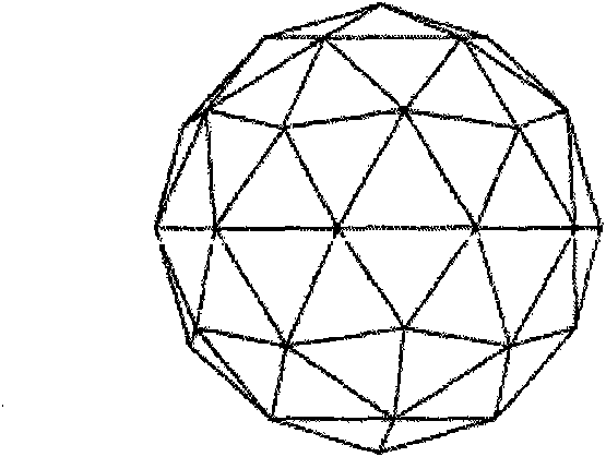
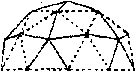
[0029] Use the 2V Geodesic Dome polyhedron to form a nearly spherical structure. As shown in Figure 1(a). 2V Geodesic Dome has 80 faces, 42 nodes, and 120 edges. Among them, 42 nodes can be divided into 5-edge connection nodes and 6-edge connection nodes according to the number of connected edges, and 120 edges can be divided into two types: long edges and short edges, respectively, as shown in Figure 1(b). As shown, the lower hemisphere is symmetrical to the upper hemisphere. In order to form a sphere, the included angles between the long side and the short side of the tangent plane of the node are different, 18 degrees and 16 degrees respectively. figure 2For the design drawing of the long-side aluminum profile designed for the present invention, since the angle between the long side and the tangent plane where the node is located is 18 degrees, the ed...


PUM


Abstract

The invention provides a 2V Geodesic Dome-based stereoscopic acquisition equipment for obtaining the optical properties of an object. When higher requirements for the drawing fidelity of a computer are required in the fields such as movie and television, digital entertainment industry and the like at present, the traditional optical models fail to describe the complex optical properties of objectsin real world. With the fast development of high-precision imaging equipment of a digital camera and the like, researchers begin researching on how to restore the optical properties of a real objectby real acquired images. According to the invention, a 2V Geodesic Dome is constructed by four-side single-notched aluminum profiles, a liftable center platform and a flexible camera or a light sourcehanging component are designed and all the components are processed by an anode aluminum oxidation process to become black and non-reflective. The camera and the light source can be hung above the Dome with the maximal hanging number being about 400, a synchronous control system is developed, and photographing of the camera, turn-on / off of the light source and rotation of a high-precision electric rotating platform can be controlled randomly via a computer. The equipment can randomly adjust the number of and the positions of the camera and the light source according to the requirements and has higher flexibility and stability.

Description

technical field [0001] The invention belongs to the technical fields of computer graphics and computer vision, in particular, it is an acquisition device for capturing images of objects under different lighting conditions, which is applied to image-based realistic material modeling, non-uniform participating medium modeling, geometric modeling etc. Background technique [0002] The interaction between objects and light in the real world has a wealth of optical phenomena, and the use of computers for realistic modeling and three-dimensional reproduction has a wide range of applications. However, measuring the optical properties of an object requires high-dimensional data to describe the reflection, refraction, or scattering process of light interacting with the object, which brings great difficulties to data collection, modeling, and real-time rendering. [0003] The illumination properties of an object are determined by the interaction between the light and the object, and ...

Claims


Application Information

Patent Timeline
Patent Type & Authority Applications(China)
IPC IPC(8): G03B35/00E04B1/32G05B19/04
Inventor 赵沁平胡勇沈方阳齐越
Owner BEIHANG UNIV
Learn More