

Liquid crystal display (LCD) device and image signal processing method
A technology for liquid crystal display device and image signal processing, applied in the field of liquid crystal display device and image signal processing, can solve the problems of low backlight brightness, low backlight brightness of monochrome images, low power consumption saving, etc., so as to avoid excessive backlight brightness. Low, good display effect
- Summary
- Abstract
- Description
- Claims
- Application Information
AI Technical Summary
Problems solved by technology
Method used
Image

Examples
Embodiment 1
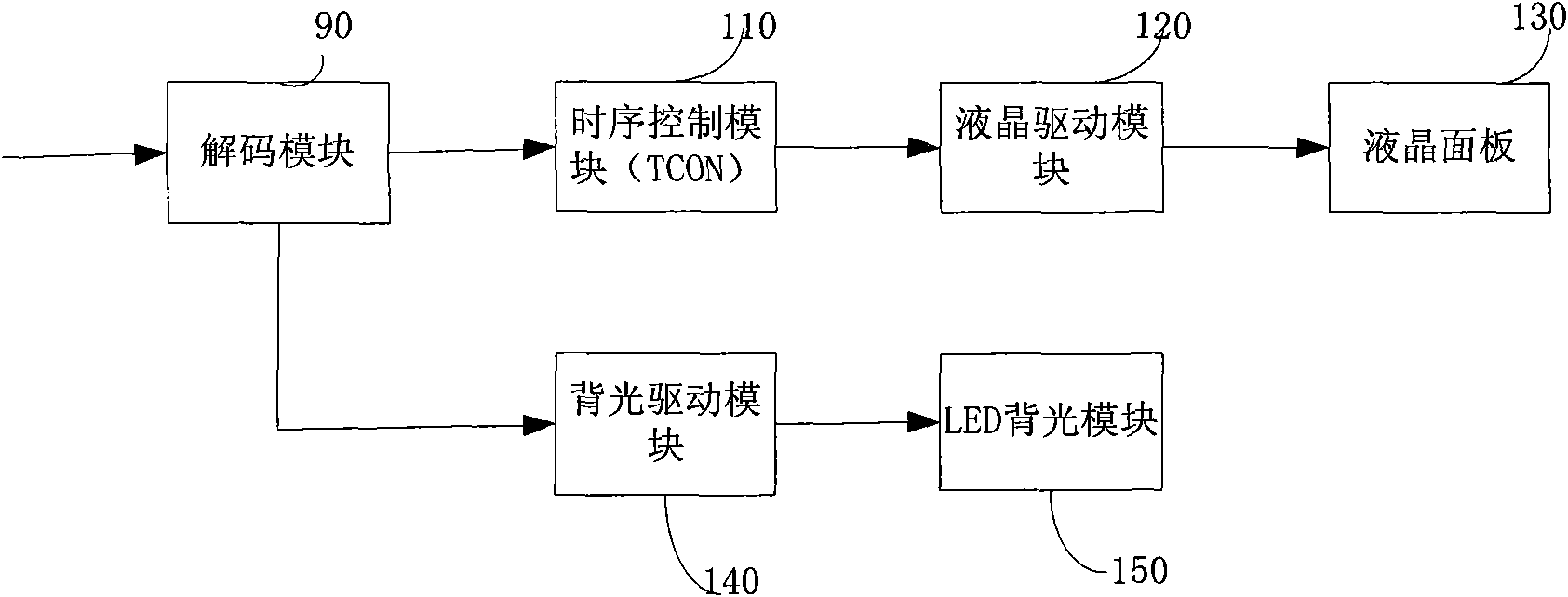
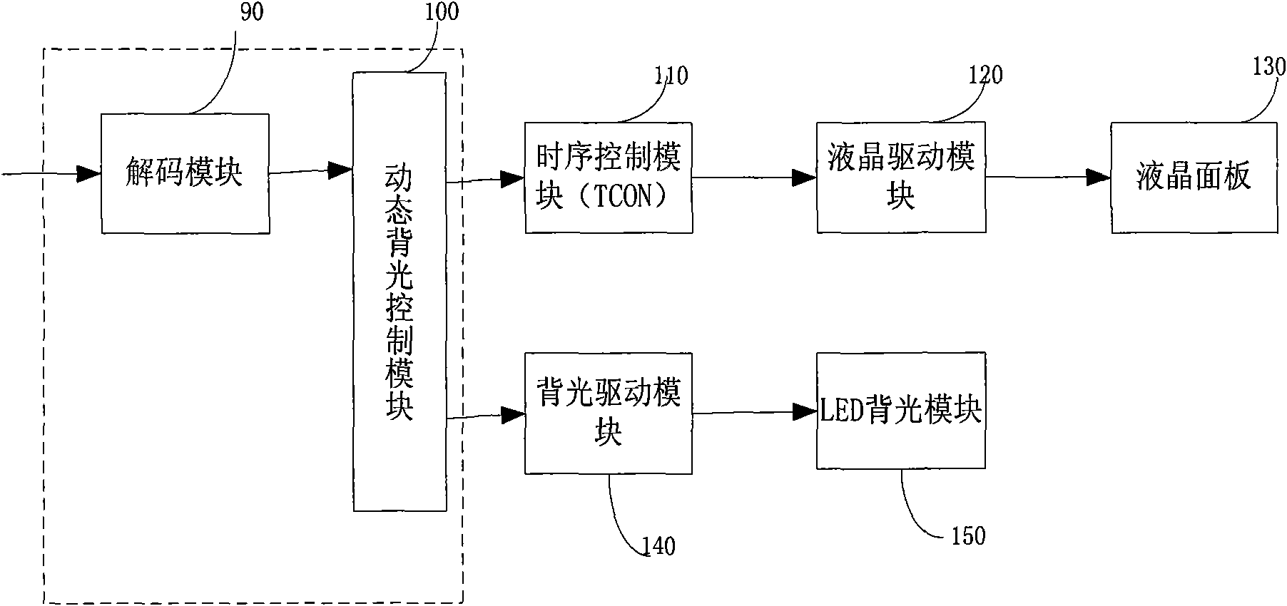
[0033] Such as figure 1 and figure 2 As shown, this embodiment provides a liquid crystal display device, including a decoding module 90, a dynamic backlight control module 100, a timing control module (timing controller, also known as a T-CON board) 110, a liquid crystal driving module 120, a liquid crystal panel 130, a backlight The drive module 140, and the LED backlight module 150, the connection relationship and functions of the above-mentioned decoding module 90, timing control module 110, liquid crystal drive module 120, backlight drive module 140, liquid crystal panel 130 and LED backlight module 150 belong to the prior art, such as figure 1 shown, and will not be repeated here. The following description focuses on the dynamic backlight control module 100 .
[0034] Such as figure 2 As shown, the dynamic backlight control module 100 is connected to the decoding module 90, of course, in order to reduce the cost, the dynamic backlight control module 100 can also be i...
Embodiment 2
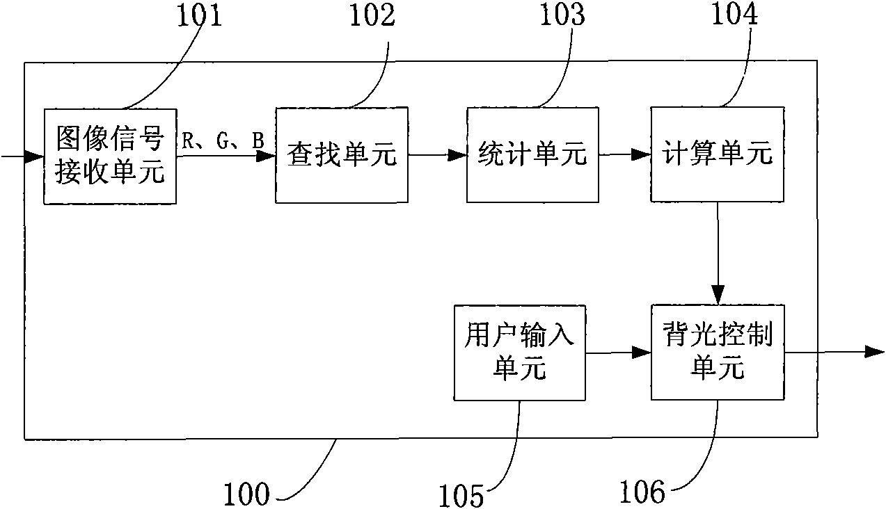
[0037] On the basis of the above examples, this embodiment provides a liquid crystal display device, such as image 3 As shown, the dynamic backlight control module 100 includes an image signal receiving unit 101 , a search unit 102 , a statistics unit 103 , a calculation unit 104 , and a backlight control unit 106 connected in sequence.
[0038] Wherein, the image signal receiving unit 101 is connected with the search unit 102 for receiving R, G, B grayscale signals in one frame of video image signal and sending them to the search unit 102 . The search unit 102 is connected to the image signal receiving unit 101 and the statistical unit 103 respectively, converts the R, G, B grayscale signals into signals R', G', B' after gamma correction, and converts the signals R', G', B' is sent to the statistical unit 103.
[0039] The statistics unit 103 is respectively connected with the search unit 102 and the calculation unit 104, and is used to calculate the average value and stand...
Embodiment 3
[0048] This embodiment provides an image signal processing method, which is applied to any of the above-mentioned liquid crystal display devices, which includes the following steps.
[0049] A1. Receive image signals R, G, B; for example, step A1 further includes the following step A11. Buffering the image signals.
[0050] A2. Perform gamma correction on the image signals R, G, and B respectively, and convert them into signals R', G', and B';
[0051] A3. Calculate the average value and standard deviation of R', G', and B' respectively; for example, calculate the average value and standard deviation of R', G', and B' by counting the histograms of R', G', and B' respectively standard deviation.
[0052] A4. Calculate the backlight adjustment value T according to each average value and each standard deviation.
[0053] For example, step A4 specifically performs the following steps:
[0054] A41. Calculate the maximum value X of the linear combination of the average value and...
PUM
 Abstract
Description
Claims
Application Information