Froot lighting lamp for vehicle

A technology for headlights and vehicles, which is applied in the direction of headlights, vehicle parts, lighting devices, etc., can solve the problems of left and right, achieve the effects of reducing the number of parts, low manufacturing cost, and improving visual recognition

Active Publication Date: 2010-03-24
ICHIKOH IND LTD
View PDF1 Cites 11 Cited by
  • Summary
  • Abstract
  • Description
  • Claims
  • Application Information

AI Technical Summary

Problems solved by technology

Therefore, the conventional vehicle headlamp has a problem that the light distribution control of the overhead sign light dist

Method used


Image

  • Froot lighting lamp for vehicle
  • Froot lighting lamp for vehicle
  • Froot lighting lamp for vehicle

Examples


Embodiment 1

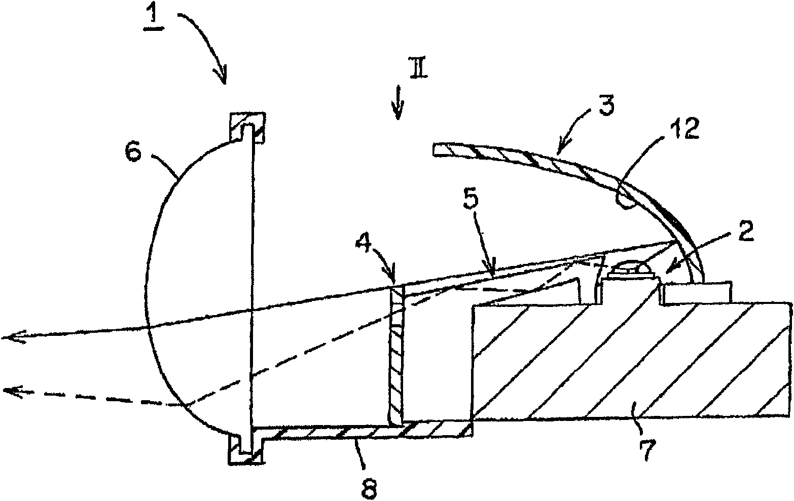
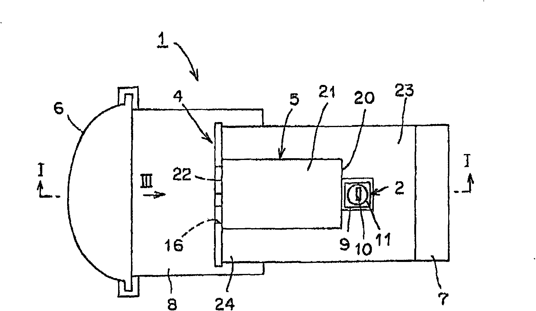
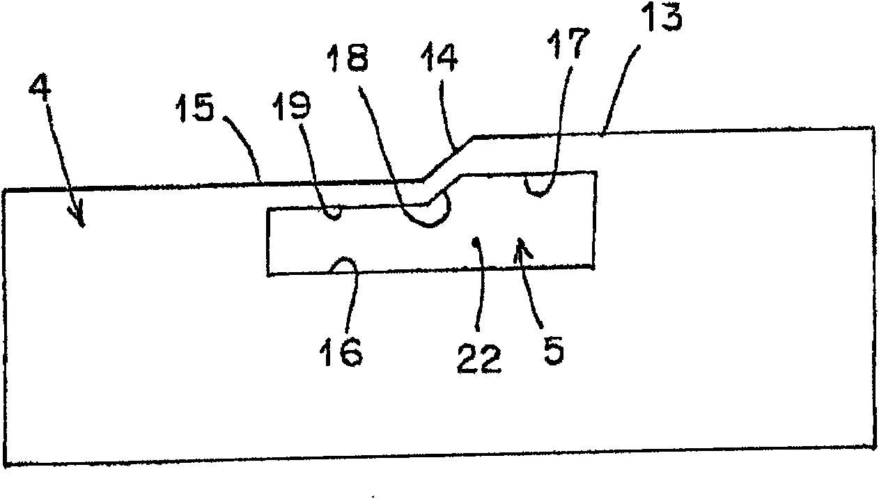
[0028] Figure 1 to Figure 5 Example 1 of the vehicle headlamp of the present invention is shown. The structure of the vehicle headlamp of the first embodiment will be described below. exist figure 1 In , symbol 1 is the vehicle headlamp in this embodiment. The vehicle headlamp 1 described above is of a projection type and constitutes a unit structure. The above-mentioned vehicle headlamp 1 includes a semiconductor-type light source 2, a reflector 3, a shade 4, a projection lens 6, a heat dissipation member 7, a holding member 8, a lamp housing and a lamp lens of an automotive headlamp not shown (for example, , plano outer lens, etc.).

[0029] The semiconductor-type light source 2 , the reflector 3 , the shade 4 , the light guide 5 , the projection lens 6 , the heat dissipation member 7 , and the holding member 8 constitute a lamp unit. One or more of the above-mentioned lamp units are disposed in a lamp chamber defined by the above-mentioned lamp housing and the above-m...

Embodiment 2

[0055] Figure 6 Example 2 of the vehicle headlamp of the present invention is shown. in the figure, with Figure 1 to Figure 5 The same symbols denote the same components. The vehicle headlamp 1A of the second embodiment will be described below.

[0056] The vehicle headlamp 1A of the second embodiment is a modified example of the vehicle headlamp 1 of the above-mentioned first embodiment. That is, in the vehicular headlamp 1 of the first embodiment described above, the light guide 5 also functions as a holding member for holding the reflector 3 , the visor 4 , the projection lens 6 , the heat dissipation member 7 , and the frame member 8 . In contrast, in the vehicle headlamp 1A of the second embodiment, the light guide body 5A and the holding member 8 are composed of different members.

[0057]That is, the light guide body 5A of the vehicle headlamp 1A of the second embodiment is composed of the incident surface 20 , the light guide portion 21 , and the exit surface 22 ...

Embodiment 3

[0062] Figure 7 ~ Figure 10 Example 3 of the vehicle headlamp of the present invention is shown. in the figure, with Figure 1 to Figure 6 The same symbols denote the same components. The vehicle headlamp 1B of the third embodiment will be described below.

[0063] The vehicle headlamp 1B of the third embodiment is a modified example of the vehicle headlamps 1 and 1A of the above-described first and second embodiments. That is, in the vehicular headlamp 1 of the first embodiment described above, the light guide 5 also functions as a holding member for holding the reflector 3 , the visor 4 , the projection lens 6 , the heat dissipation member 7 , and the frame member 8 . In contrast, in the vehicle headlamp 1B of the third embodiment, the light guide body 5B and the holding member 8 are composed of different members.

[0064] That is, the light guide body 5B of the vehicle headlamp 1B of the third embodiment is constituted by the incident surface 20 , the light guide porti...


PUM


Abstract

The present invention relates to a froot lighting lamp for a vehicle. The existing froot lighting lamp for the vehicle has a problem of light configuration control of optical patterns for aerial indication marks. The froot lighting lamp of the invention is provided with a light-guiding body (5) capable of guiding the light from a semiconductor type light source (2) to be used as the output of theoptical patterns (OP) for aerial indication marks. The light-guiding body (5) includes an incident face (20) arranged facing to the semiconductor type light source (2) and used to guide the light fromthe semiconductor type light source (2); a light-guiding part (21) used to guide the light from the incident face (20) to the prescribed position; and an emergent face (22) used to project the lightguided by the light-guiding part (21) as the optical patterns (OP) for aerial indication marks to a projection lens (6). As a result, the invention is capable of controlling the light configuration ofthe optical patterns (OP) for aerial indication marks simply.

Description

technical field [0001] The present invention relates to a projection type vehicle headlamp using, for example, a semiconductor-type light source such as an LED as a light source. Background technique [0002] Such a vehicle headlamp has been conventionally known (for example, Patent Document 1: Japanese Patent Application Laid-Open No. 2008-41271). This conventional vehicle headlamp will be described below. Existing headlights for vehicles include: a light source; a first reflective surface that reflects light from the light source to a first irradiation area; a light shielding member that shields a part of the reflected light from the first reflective surface; a second reflective surface; and a third reflective surface that reflects the reflected light from the second reflective surface toward the second irradiation area. The function of the conventional vehicle headlamp will be described below. When the light source is turned on, the light from the light source is refle...

Claims


Application Information

Patent Timeline
IPC IPC(8): F21S8/10F21V7/00F21V1/00F21V5/04F21V13/00F21W101/10F21Y101/02
CPCF21S41/147F21S41/148F21S41/24F21S41/255F21S41/43F21W2102/18
Inventor 铃木恭史
Owner ICHIKOH IND LTD
Why Eureka
Try Eureka