Fuel cell stack

A fuel cell stack and electrolyte technology, applied in the direction of fuel cell grouping, fuel cells, fuel cell additives, etc., can solve problems such as poor distribution of fuel gas and oxidant gas, voltage drop, and deterioration of starting performance

Active Publication Date: 2010-03-24
HONDA MOTOR CO LTD
View PDF1 Cites 15 Cited by
  • Summary
  • Abstract
  • Description
  • Claims
  • Application Information

AI Technical Summary

Problems solved by technology

[0011] However, there is a problem in the fuel cell stack 6 that if the operation is stopped and then started after soaking (standing) for a long time, the voltage of the module 1 close to the end plate 5 with the tube 7 in particular on the fluid supply side drops, causing the fuel cell stack 6 to start. sexual deterioration
[0012] This is because poor distribution of fuel gas and oxidant gas is likely to occur in the module 1 on the side of the pipe 7, and dew condensation water cannot be sufficiently removed on the layer 2 to be introduced into the module 1. In addition, it also affects the junction. Dew retention and uneven surface pressure, etc.

Method used


Image

  • Fuel cell stack
  • Fuel cell stack
  • Fuel cell stack

Examples


Embodiment Construction

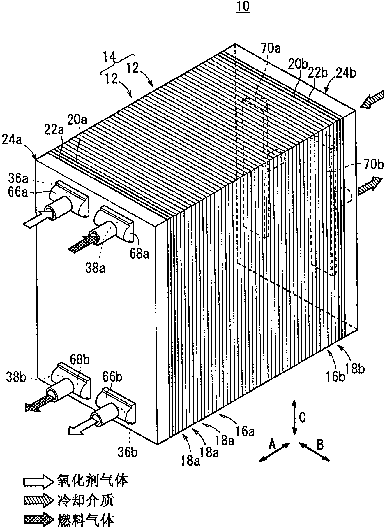
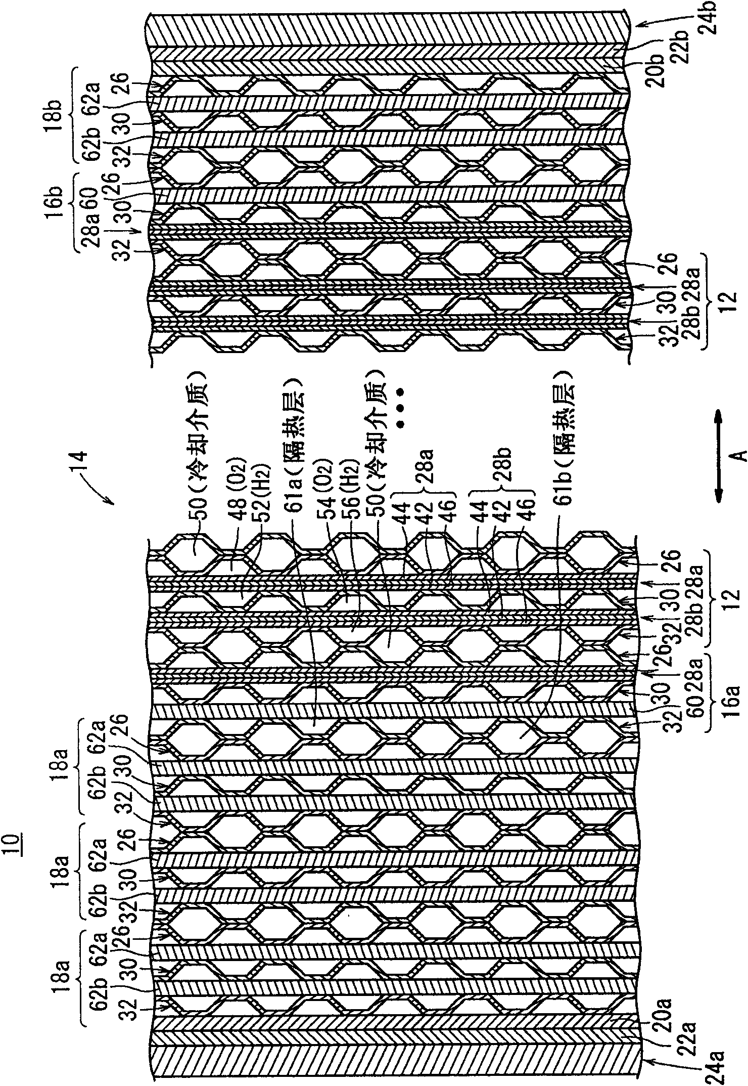
[0030] figure 1 is a schematic perspective explanatory view of a fuel cell stack 10 according to an embodiment of the present invention, figure 2 It is a cross-sectional explanatory view of main parts of the fuel cell stack 10 .

[0031] The fuel cell stack 10 includes a stacked body 14 in which a plurality of power generating units 12 are stacked in the arrow A direction. At one end of the stacked body 14 in the stacking direction, the first end power generation unit 16a and the plurality of first dummy cells 18a are arranged facing outward, and at the other end of the stacked body 14 in the stacking direction, the second end portion is disposed facing outward to generate electricity. A cell 16b and one or more second dummy cells 18b. Terminal plates 20a, 20b, insulating plates 22a, 22b, and end plates 24a, 24b are arranged facing outward on the first and second dummy cells 18a, 18b.

[0032] The fuel cell stack 10 is integrally held, for example, by a box-shaped case (n...


PUM


Abstract

The invention provides a fuel cell stack having dummy cells to achieve the desired heat insulating capability, reliably prevent condensed water from flowing into power generation units, and achieve good power generation performance with a simple structure. The fuel cell stack includes a stack body formed by stacking a plurality of power generation units. A first end power generation unit and first dummy units are provided near an end plate where reactant gas pipes for the stack body are provided. A second end power generation unit and second dummy units are provided near an end plate of the stack body on the opposite side. The number of first dummy units is larger than the number of second dummy units.

Description

technical field [0001] The present invention relates to a fuel cell stack comprising a laminated body in which power generating units are stacked, the power generating unit has an electrolyte and electrode structure in which a pair of electrodes are arranged on both sides of the electrolyte, and a separator is provided along the electrode surface reaction gas flow path, and the stacked body is formed with a reaction gas communication hole communicating with the reactant gas flow path and extending in the stacking direction of the power generation unit, and terminal plates, The insulating plate and the end plate are connected to one end plate with a reaction gas pipe communicating with the reaction gas communication hole. Background technique [0002] For example, a solid polymer fuel cell includes a power generation cell in which an electrolyte membrane and an electrode structure are sandwiched between separators. The electrolyte membrane and the electrode structure are resp...

Claims


Application Information

Patent Timeline
Patent Type & Authority Applications(China)
IPC IPC(8): H01M8/24H01M8/04
CPCH01M8/04156H01M2008/1095H01M8/0297Y02E60/50H01M8/04052H01M8/2465H01M8/2483
Inventor 古泽宏一朗名越健太郎菊池英明斗泽秀一小谷保纪
Owner HONDA MOTOR CO LTD
Why Eureka
Try Eureka