Method for determining position, laser beam detector and detector-reflector device for a system for determining position

A technology of detectors and laser beams, applied in direction/deviation determination of electromagnetic systems, active optical measuring devices, measuring devices, etc., can solve the problems of unfavorable, inaccurate and inappropriate use of GPS systems

Active Publication Date: 2010-03-24
LEICA GEOSYSTEMS AG
View PDF2 Cites 5 Cited by
  • Summary
  • Abstract
  • Description
  • Claims
  • Application Information

AI Technical Summary

Problems solved by technology

This is always very laborious and can be inaccurate and inappropriate for certain conditions, especially for measuring object

Method used


Image

  • Method for determining position, laser beam detector and detector-reflector device for a system for determining position
  • Method for determining position, laser beam detector and detector-reflector device for a system for determining position
  • Method for determining position, laser beam detector and detector-reflector device for a system for determining position

Examples


Embodiment Construction

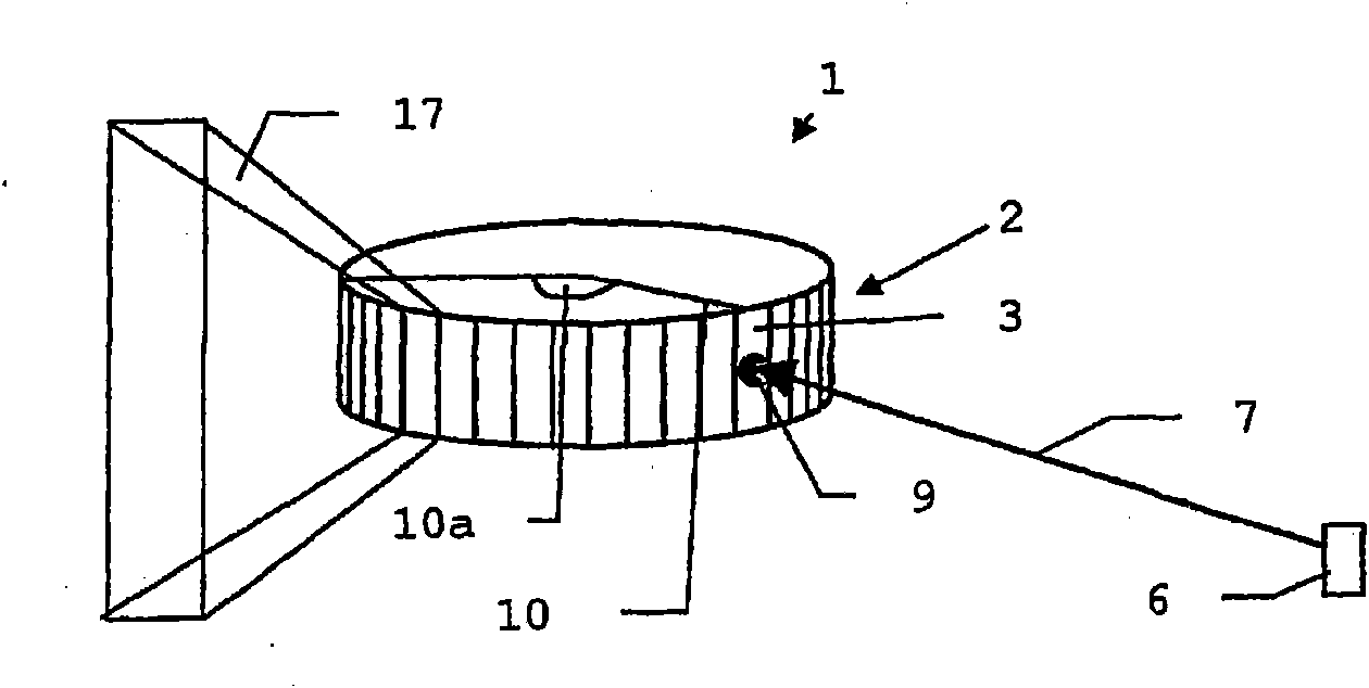
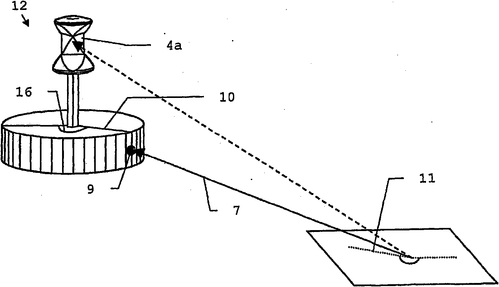
[0039] figure 1 The laser beam detector 1 is shown for determining the incident point 9 which is used for the azimuth determination method. In the method of the present invention, the laser source 6 emits the first laser beam 7 to the detector 1, where the exit direction is defined. The detector 1 detects the first laser beam 7 at about the same time.

[0040] The detector 1 has a plurality of detection areas, for example 72 detection areas, which are arranged adjacent to each other on a cylindrical surface around a vertical axis. The detection area 2 of the detector 1 is the area of ​​all the detection areas 3. Each detection area 3 covers, for example, a 5° angle range, thereby obtaining a detection area of ​​the detector 1 segmented within a 360° planar angle range, and the detection area has a corresponding number of discrete partial detection areas 17. Each partial detection area 17 is fixedly assigned a predetermined partial detection direction, for example, as a directio...


PUM


Abstract

The invention relates to a system for determining a position by emitting a first laser beam (7) by a laser source (6) positioned in a reference system onto a detector (1) and simultaneously detecting the first laser beam (7) by the detector (1), thus defining an emission direction of the laser source (7). The detector (1) has a segmented detection area comprising a plurality of discrete partial detection areas (17), each having a defined partial detection direction and at least two partial detection directions thereof being different. When detecting the first laser beam (7), an impingement point (9) of the first laser beam (7) on the detector (1) is detected by means of at least one partial detection area (17), and when determining the incidence direction (10), said direction is derived from the at least one partial detection direction. The location of the detector (1) relative to the laser source (6) and the reference system is then determined using the emission direction and the incidence direction (10).

Description

Technical field [0001] The present invention relates to an orientation determination method according to the preamble of claim 1, the application of the orientation determination method, a laser beam detector and a detector reflector device according to the preamble of claim 7. Background technique [0002] The determination of the position of an object such as a mobile machine by means of a total station, that is, the determination of the position and / or direction, has been known for a long time. Here, for example, a reflecting prism is mounted on the object at a known position relative to the object, and the reflecting prism is measured with a laser beam by means of a total station. The total station receives the reflected beam. The distance between the reflector and the total station is derived by means of the phase difference or time difference between the emitted and received beams, and the solid angle (Raumwinkel) of the object relative to the total station is detected acc...

Claims


Application Information

Patent Timeline
IPC IPC(8): G01S3/784
CPCG01S3/781G01S3/784G01S17/42G01C15/006
Inventor 汉斯约里·佩切科克劳斯·施奈德
Owner LEICA GEOSYSTEMS AG
Why Eureka
Try Eureka