

Automatic or semi-automatic cooking equipment and batch charging mechanism thereof
A technology of cooking equipment and feeding mechanism, which is applied in the field of cooking equipment, can solve problems such as the degree of freshness of raw materials is easily damaged, the quality of dishes cannot be guaranteed, and the maturity of dishes is inconsistent, so as to improve accuracy, ensure quality, and reduce labor intensity Effect
- Summary
- Abstract
- Description
- Claims
- Application Information
AI Technical Summary
Problems solved by technology
Method used
Image

Examples
Embodiment 1
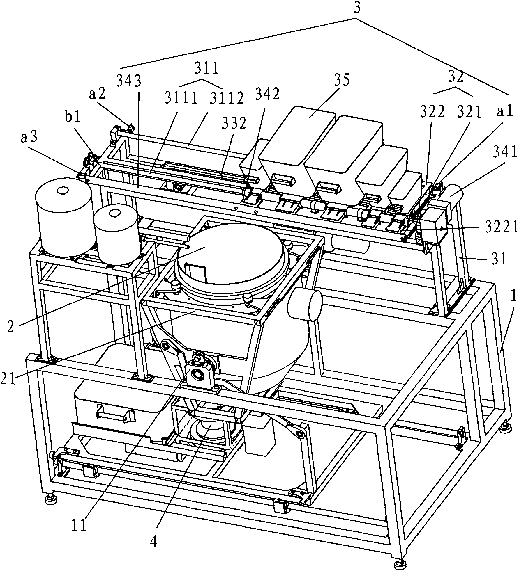
[0036] Such as figure 1 As shown, the automatic or semi-automatic cooking equipment of the present invention includes a frame 1, a pot body 2, a feeding mechanism 3, a heating device 4 and a controller (not shown in the figure).
[0037] The pot body 2 is erected on the support seat 11 of the frame 1 through the pot body bracket 21 . The feeding mechanism 3 is located above the pot body 2 . During feeding, the opening of pot body 2 faces upwards. Heating device 4 is located on frame 1, and it is positioned at the below of pot body 2.
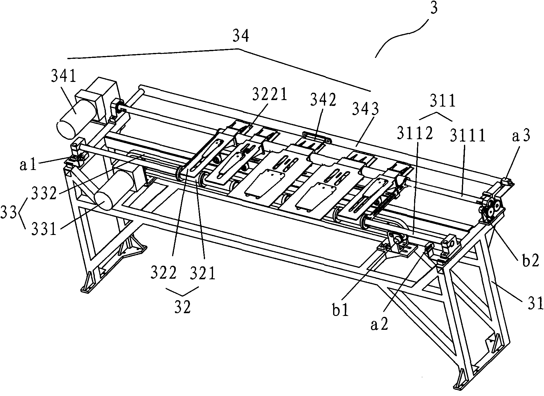
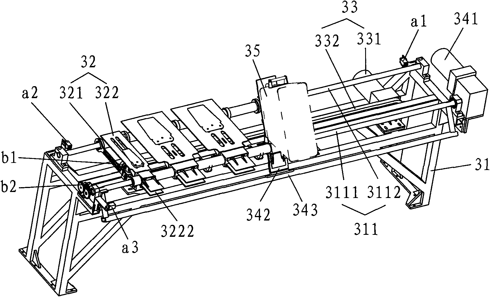
[0038] see figure 2 Feeding mechanism 3 comprises support 31 and positioning mechanism 32, and positioning mechanism 32 is installed on the support 31; The turning mechanism 34 completes the rotation feeding action of the magazine 35 .
[0039] A guide rail 311 is provided on the bracket 31, which is composed of a rail 3111 and a rail 3112 arranged in parallel.
[0040] The positioning mechanism 32 is made of a sliding seat 321 and a rota...
Embodiment 2
[0046] Such as Figure 4 , Figure 5 Shown, as another kind of scheme of the present invention, it compares with embodiment 1, and difference is:
[0047] The positioning mechanism 32 is a hollow container 32 penetrating up and down, on which a mounting groove 32a is arranged. Both sides of the material box 35 are symmetrically provided with rotating shafts 351 , and the rotating shafts 351 are supported in the installation groove 32 a on the hollow container 32 to limit the material box 35 in the hollow container 32 .
[0048] Sliders 32b are arranged symmetrically on both sides of the bottom of the hollow container 32, and a sliding groove (not shown in the figure) is arranged on the support 1, and the sliding block 32b is movably embedded in the sliding groove. The hollow container 32 is clamped on the belt 332 through the fastener 32c, and driven by it to slide on the bracket 31 .
[0049] A swing rod 352 is arranged on the feed box 35, and the swing rod 352 is fixedly ...
PUM
 Abstract
Description
Claims
Application Information