
Method and device for dynamically balanced collection of oil slick and scum

A technology of dynamic balance and collection device, which is applied in general water supply saving, water conservancy projects, cleaning of open water surface, etc. It can solve problems such as complex equipment structure, heavy maintenance workload, complicated control process, etc., achieve low energy consumption and increase oil content ratio , the effect of high collection effect

Active Publication Date: 2010-03-31
黄海峰
View PDF6 Cites 9 Cited by
  • Summary
  • Abstract
  • Description
  • Claims
  • Application Information

AI Technical Summary

Problems solved by technology

The principle of this technical solution is feasible, but in the actual working process of the equipment, the thickness of the oil-water overflow layer changes. Due to the complexity of the control process of this patent, it is difficult to adjust the thickness and liquid level of the oil-water overflow layer in time. Adjust the volume of the gas space to achieve a stable ideal working state, and the equipment structure is complicated, the maintenance workload is heavy, the manufacturing cost is high, the efficiency is not high, and it is not economically feasible
[0005] Chinese patent 01118975.4 increases the oil-water separation process, but it is still difficult to maintain the relative balance between the collector and the liquid level
[0006] In summary, none of the overflow-collecting oil slick collection methods in the prior art can effectively achieve a dynamic balance state where the injection volume and discharge volume of the collection container are constant, which makes the collection process of oil slicks difficult to be continuous and efficient. The equipment structure is complex, not economically feasible, and needs further improvement

Method used


Image

  • Method and device for dynamically balanced collection of oil slick and scum
  • Method and device for dynamically balanced collection of oil slick and scum
  • Method and device for dynamically balanced collection of oil slick and scum

Examples


Embodiment 1

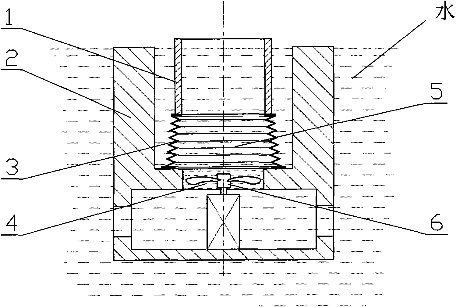
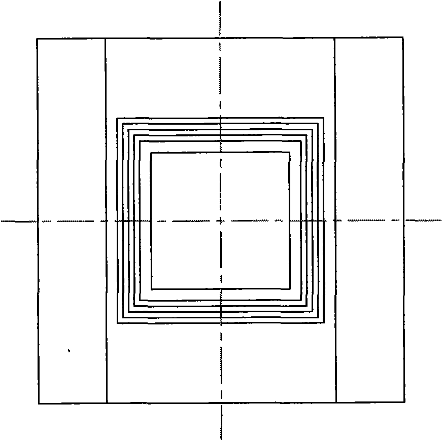
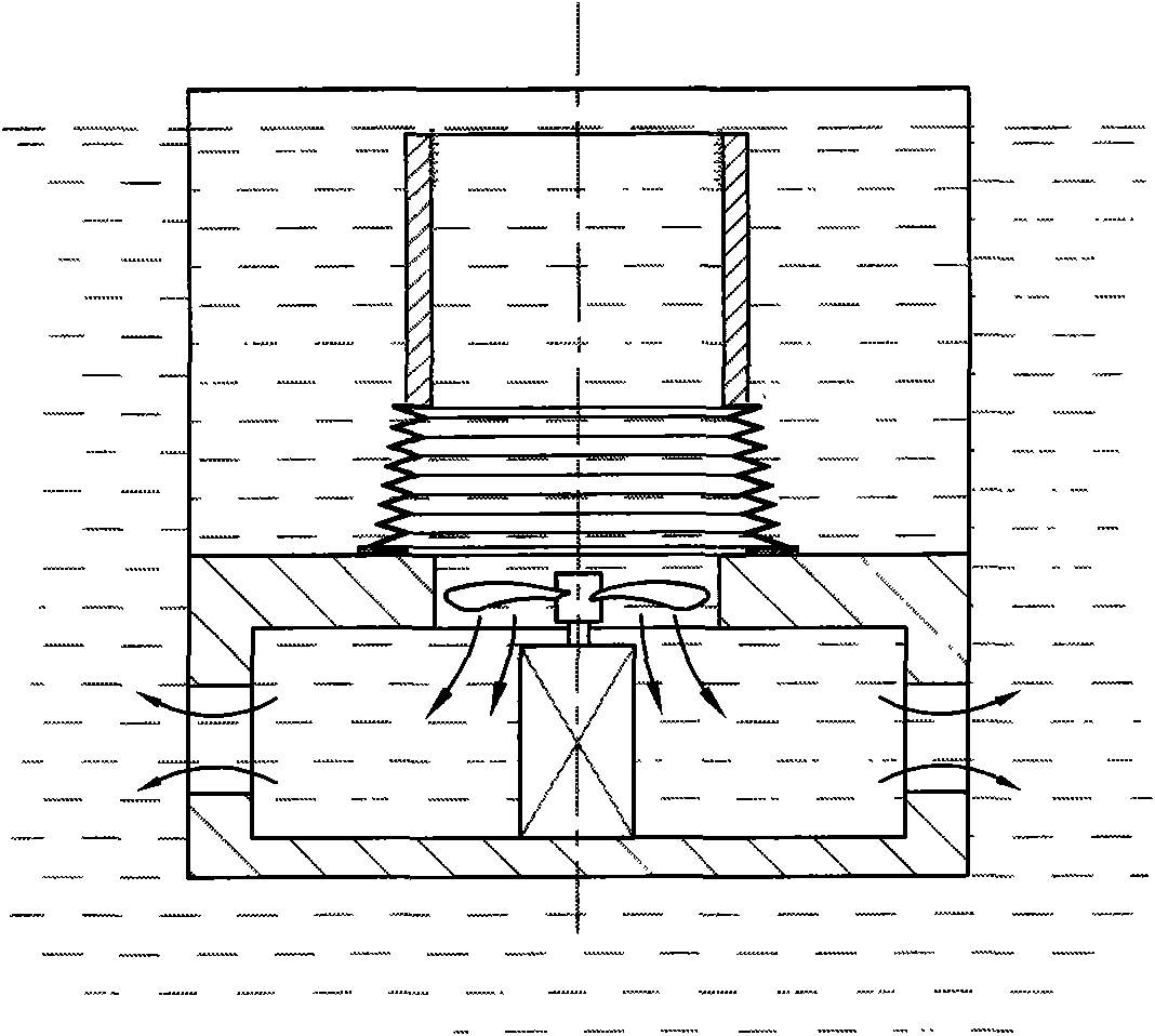
[0060] A dynamic equilibrium collection method for oil slicks and dirt, which is applied to the overflow and flow collecting oil slicks and dirt collection method in which the oil slick and dirt collection cylinder is placed upright on the water surface, and the upper part of the oil slick and dirt collection cylinder is provided with a liquid inflow channel, The lower part is provided with a liquid outflow channel, and the lower part of the collection cylinder is also provided with a closed cavity with adjustable space height, and the closed cavity communicates with the liquid outflow channel and the suction system at the lower part of the collection cylinder. A buoyancy balance component is arranged outside the collection cylinder, and the buoyancy balance component is connected with the closed cavity.

[0061] A dynamic balance collection device for floating oil and sewage, such as figure 1 , 2 As shown in , 3, it includes a collecting device and a drainage device, and the...

Embodiment 2

[0065] A dynamic equilibrium collection method for oil slicks and dirt, which is applied to the overflow and flow collecting oil slicks and dirt collection method in which the oil slick and dirt collection cylinder is placed upright on the water surface, and the upper part of the oil slick and dirt collection cylinder is provided with a liquid inflow channel, The lower part is provided with a liquid outflow channel, and the lower part of the collection cylinder is also provided with a closed cavity with adjustable space height, and the closed cavity communicates with the liquid outflow channel and the suction system at the lower part of the collection cylinder. A buoyancy balance component is arranged outside the collection cylinder, and the buoyancy balance component is connected with the closed cavity.

[0066] A dynamic balance collection device for floating oil and sewage, such as Figure 4 , 5 As shown in , 6, it includes a collecting device and a drainage device 6. The ...

Embodiment 3

[0070]A dynamic equilibrium collection method for oil slicks and dirt, which is applied to the overflow and flow collecting oil slicks and dirt collection method in which the oil slick and dirt collection cylinder is placed upright on the water surface, and the upper part of the oil slick and dirt collection cylinder is provided with a liquid inflow channel, The lower part is provided with a liquid outflow channel, and the lower part of the collection cylinder is also provided with a closed cavity with adjustable space height, and the closed cavity communicates with the liquid outflow channel and the suction system at the lower part of the collection cylinder. A buoyancy balance component is arranged outside the collection cylinder, and the buoyancy balance component is connected with the closed cavity.

[0071] A dynamic balance collection device for floating oil and sewage, such as Figure 7 , 8 As shown in , 9, it includes a collecting device and a drainage device 6. The c...


PUM


Abstract

The invention discloses a method for the dynamically balanced collection of oil slick and scum, which is a method for the overflow and flow-collecting collection of the oil slick and scum by vertically placing an oil slick and scum collecting barrel on a water surface, and is characterized in that: the upper part of the oil slick and scum collecting barrel is provided with a liquid inlet channel;the lower part of the oil slick and scum collecting barrel is provided with a liquid outlet channel and a sealed cavity with an adjustable spatial height; the sealed cavity is communicated with a liquid outlet channel at the lower part of the collecting barrel and a pumping system; a buoyancy balancing member is arranged outside the collecting barrel; and the sealed cavity is connected with the buoyancy balancing member. A device for the dynamically balanced collection of the oil slick and scum which is designed according to the method for the dynamically balanced collection comprises a flow collecting device and a water draining device, and also comprises an oil discharge device when collecting oil slick. The device has the advantages of simple structure, low energy consumption, high efficiency, no secondary pollution, wide application range and the like.

Description

technical field [0001] The invention relates to a water treatment method and a device, in particular to a method and a device for treating oil slicks and dirt on the water surface. Background technique [0002] Treating oil slicks on the water surface is a conventional method for protecting the environment, purifying water resources, and recovering renewable resources. In the prior art, there are many methods and devices for collecting oil slicks, which can be roughly divided into medium adsorption, guide Flow shoveling type, overflow collection type and other types, among which the overflow collection type is a form with relatively high efficiency. It uses an open container to float on the water surface, and uses drainage to form a liquid level difference between the inside and outside of the container. The liquid outside the container overflows into the container to collect floating oil. The overflow-collecting container of the prior art generally falls as the liquid leve...

Claims


Application Information

Patent Timeline
IPC IPC(8): E02B15/10
CPCY02A20/204
Inventor 黄海峰
Owner 黄海峰
Learn More