Electronic component unit and method for manufacturing same

A technology of electronic components and manufacturing methods, which is applied in the direction of fixed capacitance parts, electrical components, circuits, etc., can solve problems such as position deviation, inability to obtain electronic component unit characteristics, unstable position of electronic component components, etc., and achieve a suppressed position offset effect

Active Publication Date: 2010-03-31
TDK CORPARATION
View PDF1 Cites 4 Cited by
  • Summary
  • Abstract
  • Description
  • Claims
  • Application Information

AI Technical Summary

Problems solved by technology

[0004] However, in the manufacturing process of this electronic component, the position of the electronic component element in the container is unstable during the period from when the electronic component element is accommodated in the container until the molding resin material is cured, so there is a possibility that the position of the electronic component element may shift. Happening
In this way, due to the displacement of the position of the electronic component element, there may be cases where the required characteristics of the electronic component unit cannot be obtained.

Method used


Image

  • Electronic component unit and method for manufacturing same
  • Electronic component unit and method for manufacturing same
  • Electronic component unit and method for manufacturing same

Examples


no. 1 Embodiment approach

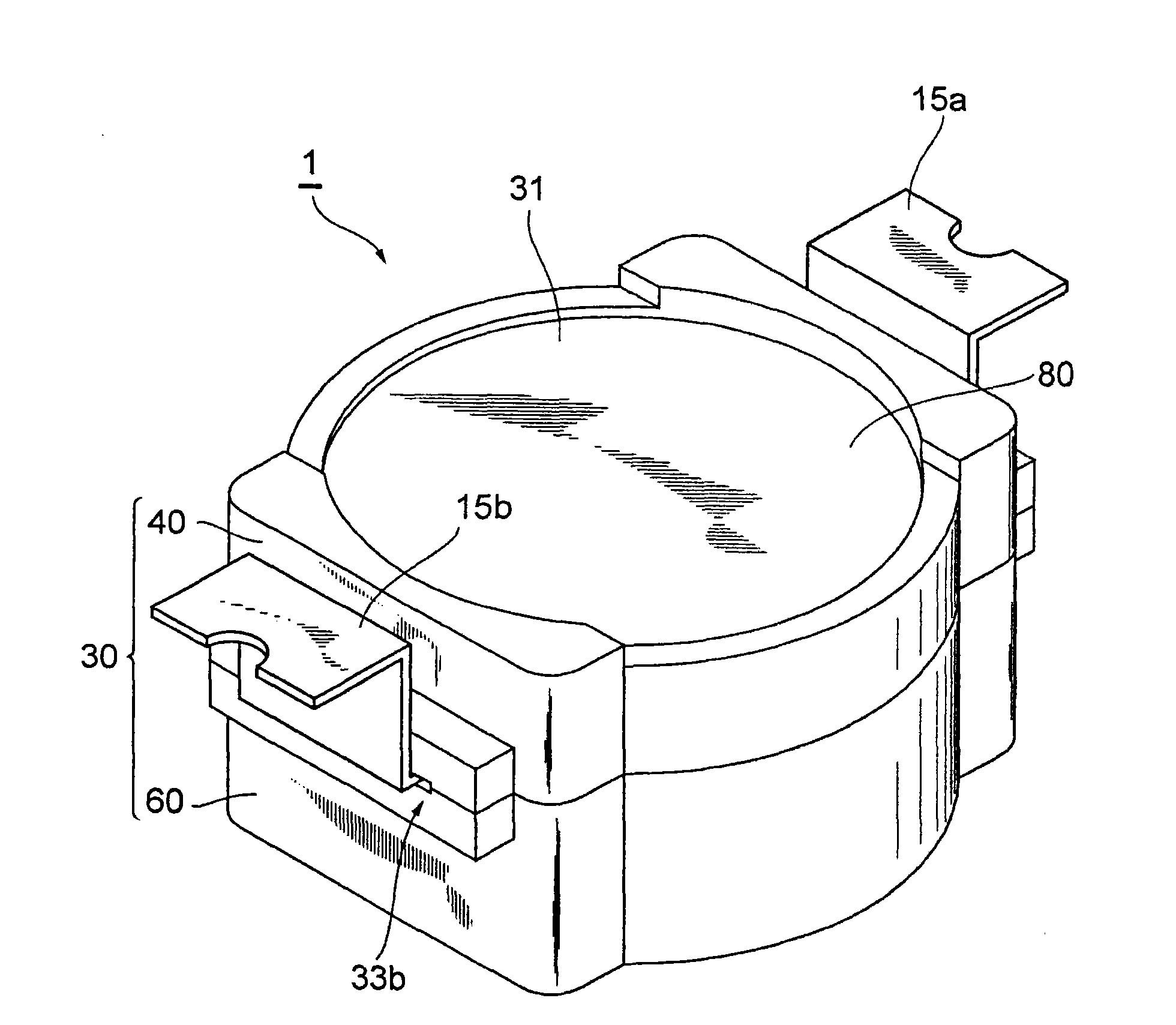
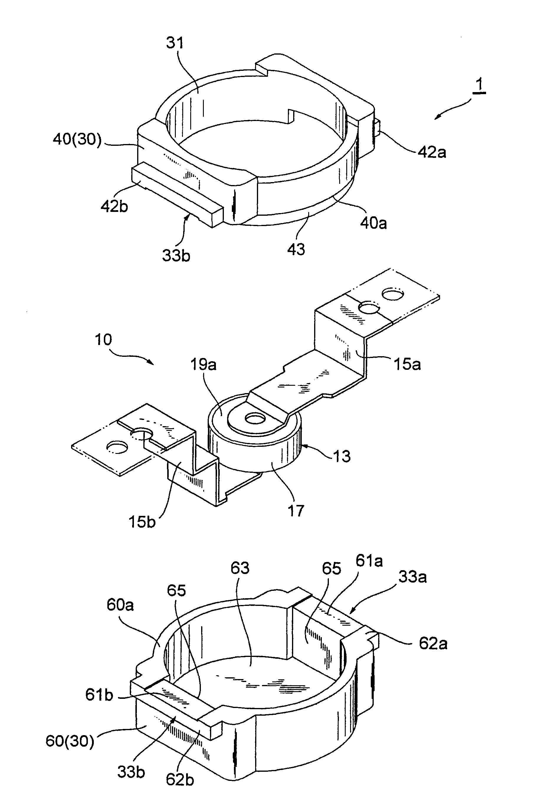
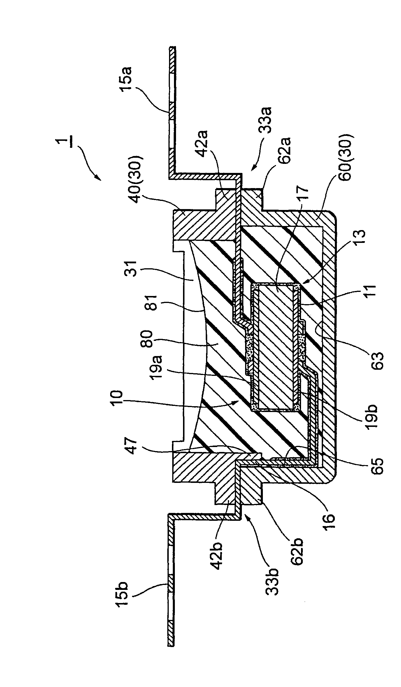
[0035] Figure 1 ~ Figure 3It shows the surface mount type capacitor unit 1 which is 1st Embodiment of the electronic component unit which concerns on this invention. The capacitor unit 1 is an injection type resin-molded medium-voltage capacitor unit, and includes a capacitor portion (electronic component) 10 and an exterior container 30 accommodating the capacitor portion 10 . This capacitor unit 1 is formed by accommodating the capacitor part 10 in the outer container 30 with its lead frames (metal terminals) 15a, 15b exposed outside the outer container 30, and performing resin molding on the inside of the outer container 30. electronic components unit. The capacitor unit 1 will be described in detail below.

[0036] The exterior container 30 is composed of two parts, namely, an exterior cup (second part) 60 and an exterior cap (first part) 40 separated up and down. Both the exterior cover 40 and the exterior cup 60 are formed of a plastic material such as LCP (liquid cr...

no. 2 Embodiment approach

[0069] Such as Figure 14 As shown, the exterior container 103 of the capacitor unit 101 is composed of two parts: an exterior cup (first part) 160 and an exterior cover (second part) 140 separated into upper and lower parts. The exterior cup 160 is in the shape of a circular bottomed cup with an open top, and the exterior lid 140 is in the shape of a cylinder having substantially the same diameter as the exterior cup 160 .

[0070] The exterior cup 160 has a protrusion 167 that extends upward from the bottom surface 163 and is inserted into the exterior lid 140 . The lead frame 15 a is pressed against the inner wall side surface 145 of the exterior cover 140 through the protrusion 167 , and is sandwiched between the inner wall side surface 145 and the outer side surface of the protrusion 167 . In addition, when viewed from the surface electrode 19b, the protrusion 167 exists between the closest position 116 of the lead frame 15a and the surface electrode 19b. That is, the c...


PUM


Abstract

The inventive capacitor unit is characterized by comprising a capacitor part and an external container for accommodating the capacitor part, and forming by resin casting in the external container through a condition that the front end of a leadframe is exposed out of the outside of the external container. The external container is provided with an external cover and an external cup, the external cover is provided with protrusions extending to the side of the external cup on the inner side of the external container. The front end of the leadframe is led out to the outside of the external container from between the external cover and the external cup, and the leadframe is sandwiched by the inner wall side of the external cup and the protrusions.

Description

technical field [0001] The present invention relates to an electronic component unit formed by accommodating an electronic component in a container and resin-molding the inside of the container, and a method for manufacturing the electronic component unit. Background technique [0002] Conventionally, the electronic component unit described in Japanese Utility Model Application Laid-Open No. 2-79020 has been known as a technique in such a field. This electronic component unit is an electronic component unit in which electronic components such as capacitors are housed in a container and the inside of the container is resin-molded. In the manufacture of this electronic component unit, the electronic component is accommodated in a container with an open top, and a molding resin material is injected into the container and cured in a state where the metal terminals extending from the electrodes of the electronic component are drawn out of the container. . Furthermore, the elect...

Claims


Application Information

Patent Timeline
Patent Type & Authority Applications(China)
IPC IPC(8): H01G4/00H01G4/228H01G4/224
CPCH01G2/06H01G2/10H01G2/14H05K1/181
Inventor 三浦严坂本典正工藤仁榊原将人
Owner TDK CORPARATION
Why Eureka
Try Eureka