Semi-automatic laminating method of electrical core of power battery and laminating equipment thereof

A power battery, semi-automatic technology, applied in the direction of secondary batteries, circuits, electrical components, etc., can solve the problems of high assembly adjustment skills, long time, high operation intensity, etc., to reduce the proficiency requirements, reduce equipment costs, The effect of reducing the intensity of the operation

Active Publication Date: 2010-03-31
SHENZHEN GEESUN INTELLIGENT TECHNOLOGY CO LTD
View PDF0 Cites 18 Cited by
  • Summary
  • Abstract
  • Description
  • Claims
  • Application Information

AI Technical Summary

Problems solved by technology

With the fully manual stacking method, the diaphragm has no tension, the stacked cells are in the shape of tiles, the diaphragms on both sides are not folded properly, and the operation intensity is high; the automatic stacking method is adopted, the equipment cost is high, and the assembly and adjustment skills are high. , and when replacing the cell model, it needs to be reassembled and adjusted, which takes a long time

Method used

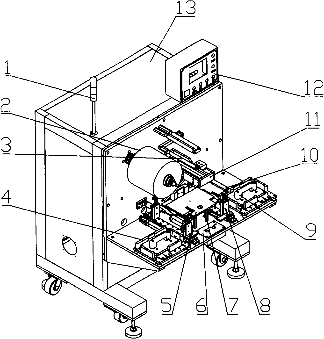
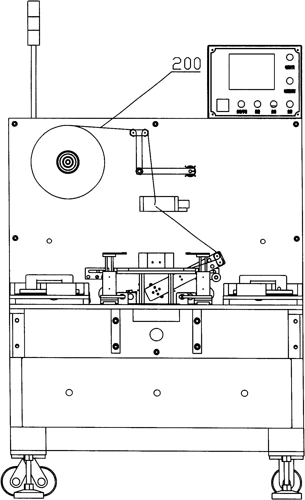
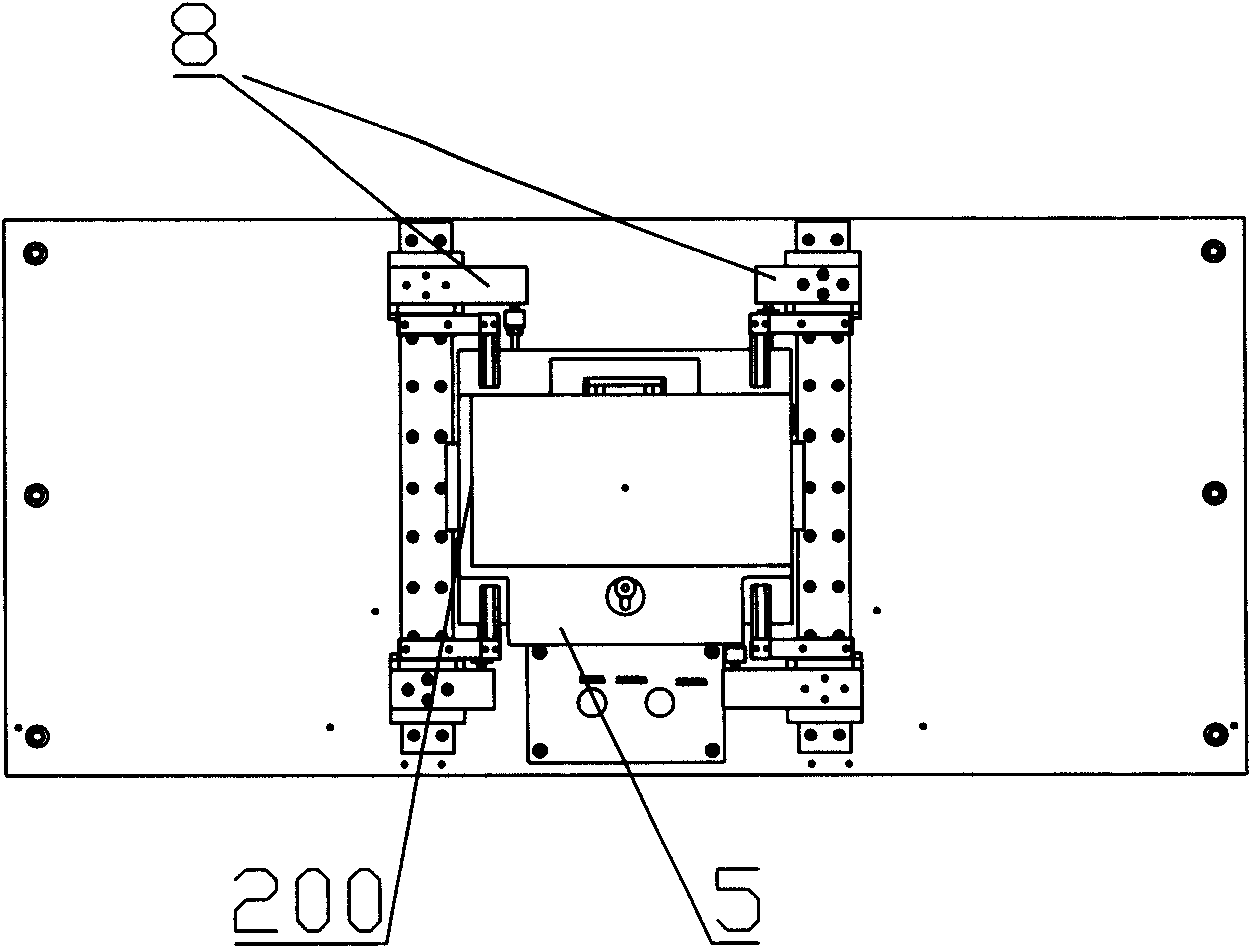

Image

  • Semi-automatic laminating method of electrical core of power battery and laminating equipment thereof
  • Semi-automatic laminating method of electrical core of power battery and laminating equipment thereof
  • Semi-automatic laminating method of electrical core of power battery and laminating equipment thereof

Examples


Embodiment Construction

[0089] A semi-automatic lamination method for power battery cells, comprising the following steps:

[0090] 1) Pull and place the base layer diaphragm on the surface of the cell movable plate;

[0091] according to figure 2 Thread the diaphragm 200 as shown, and pull the diaphragm to a suitable position on the cell fixing plate 5 that exceeds the width of the pole piece. On the man-machine interface, select the manual mode, and then turn left on the button plate 6 Knob 601, the left pole clip 8 moves to clamp the diaphragm, and its clamping state is as follows Figure 4 As shown; same as it, turn the knob 601 on the button plate 6 to the right, the right pole clip 8 moves, and the diaphragm is clamped. Such as Figure 15 shown. After doing the above actions, select the automatic mode on the man-machine interface.

[0092] 2) Laying the first cathode sheet on the surface of the base layer separator;

[0093] Press the button 904 on the left suction cup assembly 9, the su...


PUM


Abstract

The invention relates to a semi-automatic laminating method of an electrical core of a power battery and laminating equipment thereof. The method comprises the following steps: (1) stretching a diaphragm on the base layer; (2) laminating a first cathode piece; (3) winding a diaphragm on the first layer; (4) laminating a first anode piece; (5) winding a diaphragm on the second layer; (6) cyclicallyoperating step (2) to step (5) until the numbers of the laminated pieces and the wound diaphragms reach the set numbers of pieces and layers; and (7) taking out the laminated electrical core, whereinstep (3) and step (5) are carried out in an automatic mode, and other steps are carried out in a manual mode. A diaphragm winding component of the equipment controls a servo motor through a pedal switch, and controls the positioning of a diaphragm winding roller through a photoelectricity eye sensitive film; manual sucking discs at the left side and the right side suck pole pieces in a cathode piece box and an anode piece box at the left side and the right side by the vacuum generated by a vacuum valve through a vacuum sucking plate, and the pole pieces are laminated on the surfaces of the diaphragms which are wound to finish laminating; and then, the diaphragm winding component winds to the same side to automatically wind the diaphragms on the surfaces of the pole pieces. The invention can enable the diaphragms to be basically controlled in constant tension, relieve the operating strength, is convenient for replacing models and reduces the equipment cost.

Description

technical field [0001] The invention relates to a battery lamination method and equipment, in particular to a semi-automatic lamination method and lamination equipment for power battery chips. Background technique [0002] There are two methods for the production of power battery cells: one is fully manual, which involves manually stacking the cathode and anode sheets and manually winding the diaphragm; the other is fully automatic, including automatically stacking the cathode and anode sheets , Automatic winding and unwinding of the diaphragm, automatic outer winding of the diaphragm and automatic gluing. With the fully manual stacking method, the diaphragm has no tension, the stacked cells are in the shape of tiles, the diaphragms on both sides are not folded properly, and the operation intensity is high; the automatic stacking method is adopted, the equipment cost is high, and the assembly and adjustment skills are high. , and when changing the cell model, it needs to be...

Claims


Application Information

Patent Timeline
Patent Type & Authority Applications(China)
IPC IPC(8): H01M10/38
CPCY02E60/12Y02E60/10Y02P70/50
Inventor 范方才陈明强
Owner SHENZHEN GEESUN INTELLIGENT TECHNOLOGY CO LTD
Why Eureka
Try Eureka